Return to Section TOC

Return to Section TOC

Return to Section TOC

Return to Section TOC

Return to Master TOC

Return to Master TOC

Return to Master TOC

Return to Master TOC

G-6

ELECTRICAL DIAGRAMS

G-6

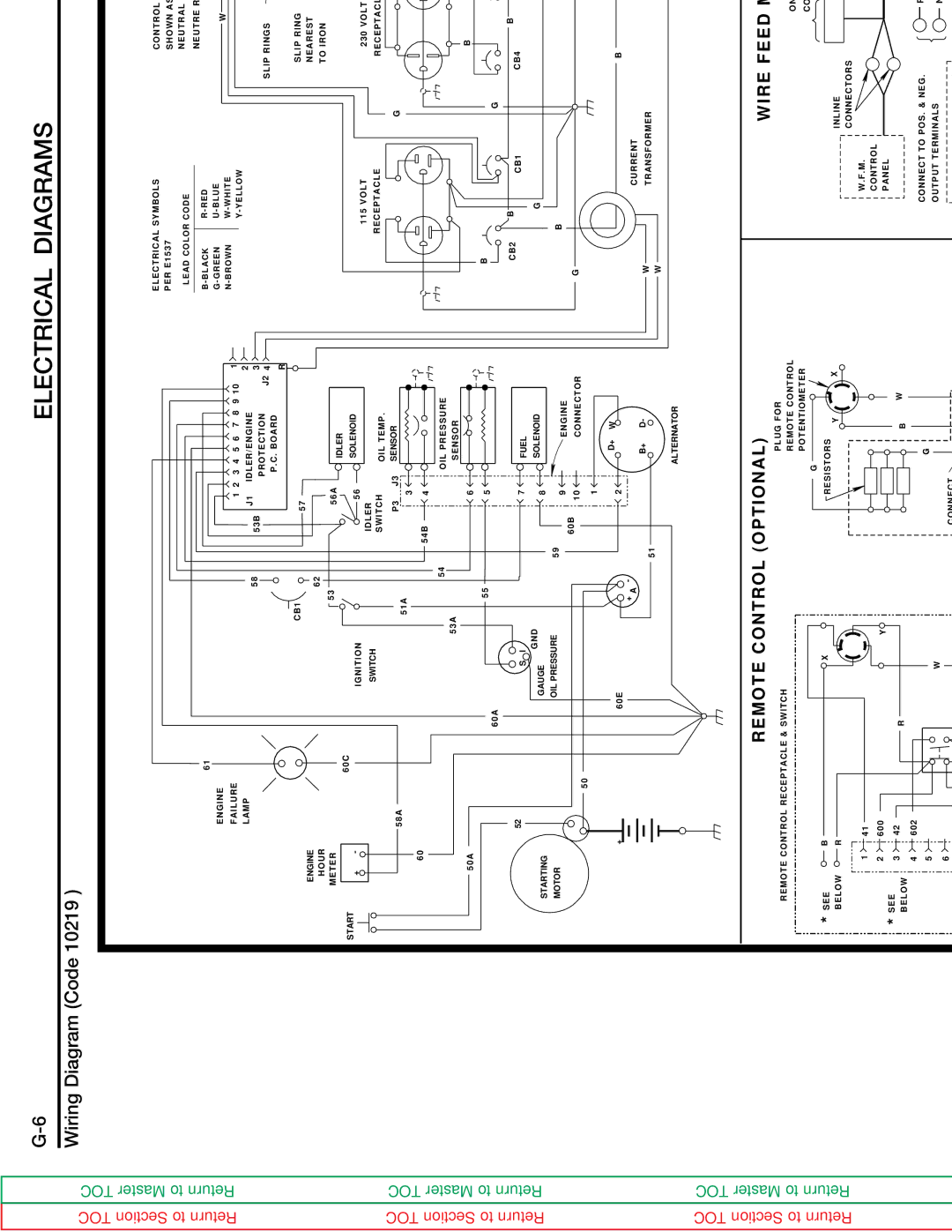
Wiring Diagram (Code 10219 )


ELECTRICAL SYMBOLS

CONTROL PANEL COMPONENTS


PER E1537


SHOWN AS VIEWED FROM REAR.


P10


LEAD COLOR CODE

NEUTRAL BONDED TO FRAME


NEUTRE RACCORDE 'AU BATI


12 11 10 9 8

7 6 5

4 3 2 1


61


B-BLACK

R-RED


J5


ENGINE


G-GREEN

U-BLUE


W


N-BROWN

W-WHITE


B


+Y


FAILURE


1 2

3 4

5 6

7

8

9 10

1


Y-YELLOW


N


LAMP


IDLER/ENGINE


2


ALTERNATOR

ROTOR


-W


58

53B

J1


U


3


PROTECTION

J2

4


SLIP RINGS


-


P.C. BOARD


+


R


B


610


+


CB1


57


SLIP RING


ENGINE


62


NEAREST


R


610

602B


HOUR


53


TO IRON


AC


AC


600B


56A


METER

60C


IDLER


START


41


1


+

-

IGNITION


56


SOLENOID


-


115 VOLT


230 VOLT


600A


2


SWITCH


IDLER


Y


OIL TEMP.


RECEPTACLE

RECEPTACLE


42


3


SWITCH


15A.


58A


51A


P3

J3

SENSOR


G


Y


4


FUSE


602A


3


5


60


54B

4


RHEOSTAT


6


53A

54


OIL PRESSURE


Y


J8


P9


SENSOR


B


B


SELECTOR


50A


6


R


SWITCH


55


B


60A


5


G


ALTERNATOR


CB2

B


B

CB3

W


52

S I


7


FUEL


CB1

CB4

AUXILIARY


GND


POWER


STARTING


GAUGE


8


SOLENOID


G


WINDINGS


GENERATOR


MOTOR


OIL PRESSURE

59


9


ENGINE


B


60B


G


50


10


CONNECTOR


A


1


B


+


60E


2


D+

W


B


5 4 3

2 1


+ A

-


B+

D-


W


CURRENT


CR2 REED


WELDER


51


TRANSFORMER


RELAY


LEAD BLOCK


W


R


N


ALTERNATOR


U

-W+Y


N


POSITIVE


NEGATIVE


(CC- )

(CC+) & (CV+ WITH W.F.M.)


REMOTE CONTROL (OPTIONAL)


WIRE FEED MODULE (OPTIONAL)


REMOTE CONTROL RECEPTACLE & SWITCH


PLUG FOR


REMOTE CONTROL


ON MACHINE, REMOVE PLUG "P10" FROM CONNECTOR "J5".


G

POTENTIOMETER


CONNECT PLUG "P5" ON W.F.M. TO CONNECTOR "J5" ON MACHINE.


* SEE


B


X


RESISTORS

Y


X


INLINE


PLUG


￿

BELOW

R


CONNECTORS


(P5)


.


1

41


W.F.M.


.

* SEE

2

600


Y


CONTROL


W


PANEL


3

42

R


B


.

BELOW

4

602


#8 LEAD


WIRE

FEED


CONNECT TO POS. & NEG.


POS.


G


5


W


6


OUTPUT TERMINALS


NEG.


MODULE


TO CASE


NEGATIVE CV


P8


CONNECT


OUTPUT TERMINAL


#2 HEAVY LEAD


SWITCH FOR LOCAL OR REMOTE CONTROL


PANEL


608


,


SHOWN IN LOCAL POSITION.


CONNECT TO NEG.


609


REMOTE CONTROL


* WITH MACHINE NOT RUNNING,

REMOVE PLUG "P9" ON


.


BRUSH HOLDER


POTENTIOMETER BOX


#2 HEAVY LEAD


MACHINE FROM CONNECTOR "J8". THEN CONNECT


PLUG "P8" ON REMOTE CONTROL TO


THERMOSTAT * MACHINE MUST NOT BE RUNNING


RED & BLACK LEADS NOT CONNECTED ON THIS


CONNECTOR "J8" ON MACHINE.


250 AMP


WHEN MAKING THESE CONNECTIONS.


MACHINE.


ASSEMBLY


R


1-19-96


CLEVELAND, OHIO U.S.A.


L9920

NOTE: This diagram is for reference only. It may not be accurate for all machines covered by this manual. The wiring diagram specific to your code is pasted inside one of the enclosure panels of your machine.

CLASSIC II

Page 105
Image 105
Lincoln Electric SVM125-A service manual Thermostat * Machine Must not be Running

SVM125-A specifications

The Lincoln Electric SVM125-A is a versatile and highly efficient welding machine that has gained significant recognition in the welding industry. Designed for both professionals and enthusiasts, this machine combines advanced technology with user-friendly features to deliver outstanding performance in a range of welding applications.

One of the standout features of the SVM125-A is its Inverter Technology. This cutting-edge technology allows for lightweight and compact design, making the machine highly portable. The inverter technology also provides a steady arc, which is crucial for achieving clean, high-quality welds. With a duty cycle of 125 amps at a 60% duty cycle, this welding machine can handle a variety of materials and thicknesses, from thin sheet metal to heavier structural components.

The SVM125-A supports multiple welding processes, including MIG, stick, and TIG welding. This versatility makes it an ideal choice for diverse welding tasks, whether you're working in a fabrication shop, doing repair work, or engaged in hobbyist projects. The machine features easy switch functionality, allowing users to quickly shift between welding processes without complicated setup.

Another notable characteristic is the machine's user-friendly interface. The intuitive control panel includes clear indicators and knobs that allow for easy adjustments of voltage and wire feed speed. This design is especially helpful for novice welders, providing them with the confidence to make adjustments as needed and ensuring optimal weld quality.

Safety is also a priority with the SVM125-A. The machine is equipped with thermal overload protection, which automatically shuts it down in case of overheating, preventing damage to the unit and ensuring operator safety. Additionally, the machine features a robust construction that emphasizes durability, making it suitable for demanding work environments.

Portability is enhanced through its lightweight design, and the built-in carrying handle makes it easy to transport from one job site to another. The SVM125-A is also compatible with a variety of welding accessories, further increasing its adaptability and functionality.

In conclusion, the Lincoln Electric SVM125-A stands out as a well-rounded welding machine that integrates advanced technology with user-friendly features. Its versatility in welding processes, robust design, and emphasis on safety and usability make it a valuable tool for welders at all skill levels. Whether for professional use or personal projects, the SVM125-A is a reliable choice that delivers exceptional performance and quality.