POWER, BATTERY, & GROUND WIRING
Power Wiring
✦NOTE: DO NOT APPLY POWER UNTIL THE INSTALLATION IS COMPLETE.
1.Route two wires between the
•For power wire runs up to 100 feet, use 18 AWG, THHN
•For power wire runs up to 200 feet, use 16 AWG, THHN
2.Connect the wires to the transformer. Connect the other end of the wires to the two
Backup Battery
Use of battery backup is optional. It will allow the
five telephones are connected. The door or gate access device must use some type of battery backup for the entire system to be functional.
Backup batteries will not fit into the
✦NOTE: Backup batteries are not required to maintain the
1.Route two wires between the RE-1 and the backup batteries.
2.Connect two 1.2 Amp/hour (minimum),
3.Connect the Battery #1 positive to the
4.Connect the Battery #2 negative to the
✦NOTE: The
Earth Ground
For the best ground, use size 12 gauge solid wire or larger to connect the to an
1.Connect the
2.Connect the Telephone Bypass Module EARTH GROUND terminal to the earth ground wire.
OPTIONAL REMOTE KEYPAD
The optional Model
1.Mount the
2.Route
•For wire runs up to 300 feet use 24 AWG Belden Type 9931 or equivalent.
•For wire runs up to 600 feet use 20 AWG Weico Type 9405 or equivalent.
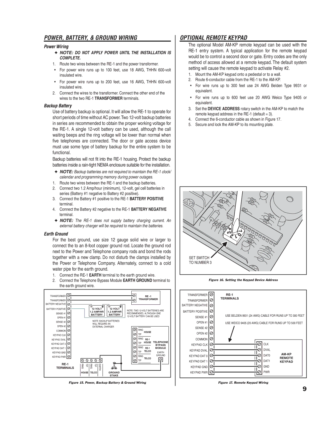
3.Set the DEVICE ADDRESS rotary switch in the
4.Connect the
5.Secure and lock the
SET SWITCH |
TO NUMBER 3 |
Figure 16. Setting the Keypad Device Address
TRANSFORMER
TRANSFORMER
BATTERY NEGATIVE
BATTERY POSITIVE
SENSE #1
OPEN #1
SENSE #2
OPEN #2
COMMON
KEYPAD CLK
KEYPAD DVAL
KEYPAD DAT 0
KEYPAD DAT 1
KEYPAD GND
KEYPAD PWR
TERMINALS
|
|
|
|
|
|
|
|
|
|
|
|
|
| 12 VOLT |
|
| 12 VOLT | ||||||||
1.2 AMP/HR |
| 1.2 AMP/HR | ||||||||||
| BATTERY |
|
| BATTERY | ||||||||
NOTE: BACKUP BATTERIES
WILL REQUIRE AN
EXTERNAL CHARGER
TIP RING | TIP RING | EARTH |
HOUSE | TELCO | GROUND |
|
| STAKE |
RE
TRANSFORMER
NOTE: TWO
RING | HOUSE |
|
TIP |
| |
|
| |
RING | TELEPHONE | |
TIP | HOUSE | |
RING |
| BYPASS |
MODULE | ||
TIP | TELCO | EARTH |
|
| |
RING |
| GROUND |
TELCO |
| |
TIP |
| |
|
|
TRANSFORMER TRANSFORMER BATTERY NEGATIVE BATTERY POSITIVE SENSE #1 OPEN #1 SENSE #2 OPEN #2
COMMON
KEYPAD CLK
KEYPAD DVAL
KEYPAD DAT 0
KEYPAD DAT 1
KEYPAD GND
KEYPAD PWR
TERMINALS
USE BELDEN 9931 (24 AWG) CABLE FOR RUNS UP TO 300 FEET
USE WEICO 9405 (20 AWG) CABLE FOR RUNS UP TO 500 FEET
CLK
DVAL
DAT0
REMOTE
DAT1 KEYPAD
GND
PWR
Figure 15. Power, Backup Battery & Ground Wiring
Figure 17. Remote Keypad Wiring
9