OPTIONAL CCTV CAMERA
Linear’s Model
The camera is continuously powered by the
The RE
The
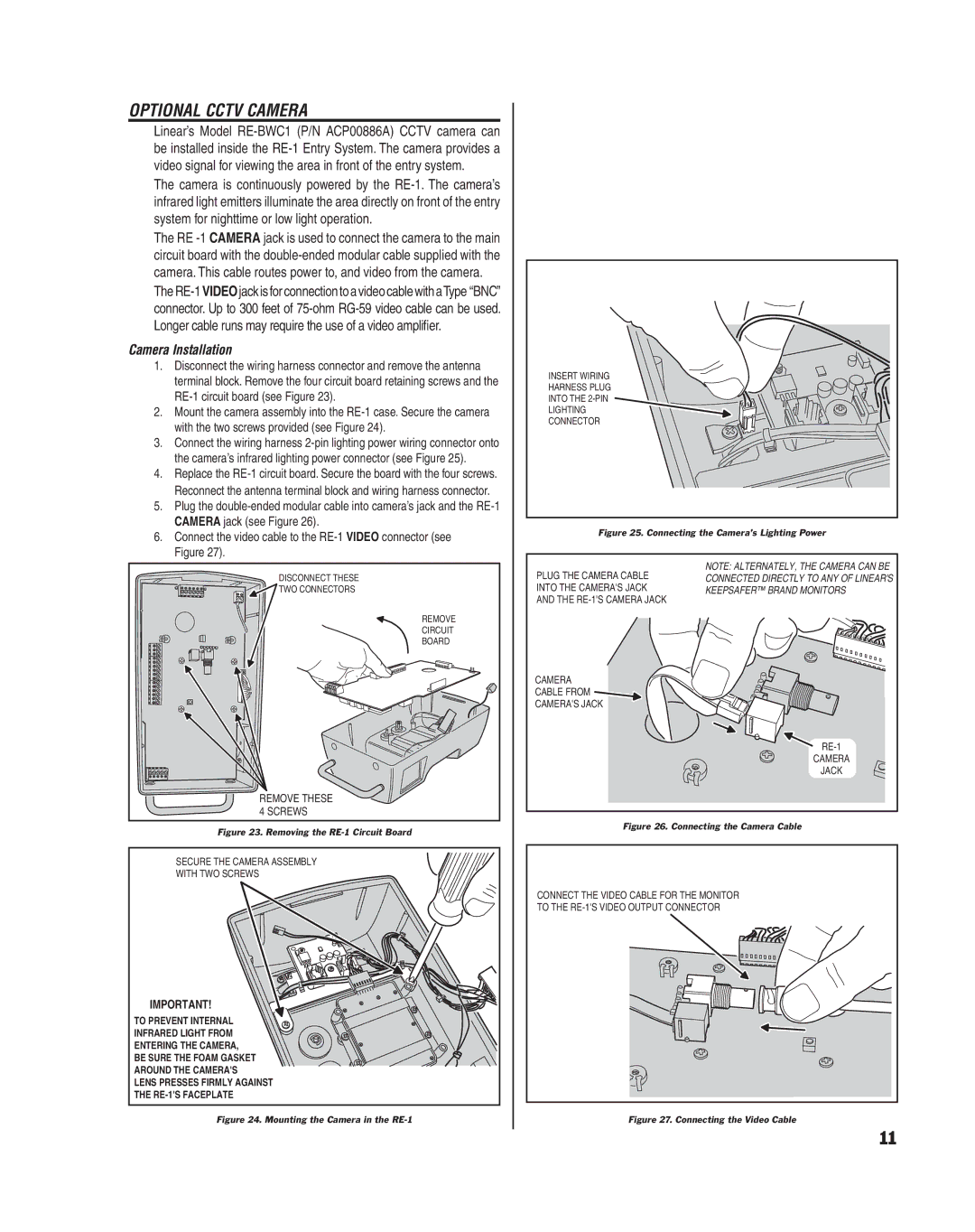
Camera Installation
1.Disconnect the wiring harness connector and remove the antenna terminal block. Remove the four circuit board retaining screws and the
2.Mount the camera assembly into the
3.Connect the wiring harness
4.Replace the
5.Plug the
6.Connect the video cable to the
DISCONNECT THESE |
TWO CONNECTORS |
REMOVE |
CIRCUIT |
BOARD |
REMOVE THESE |
4 SCREWS |
Figure 23. Removing the RE-1 Circuit Board
SECURE THE CAMERA ASSEMBLY
WITH TWO SCREWS
IMPORTANT!
TO PREVENT INTERNAL
INFRARED LIGHT FROM
ENTERING THE CAMERA,
BE SURE THE FOAM GASKET
AROUND THE CAMERA'S
LENS PRESSES FIRMLY AGAINST
THE
Figure 24. Mounting the Camera in the RE-1
INSERT WIRING
HARNESS PLUG
INTO THE
LIGHTING
CONNECTOR
Figure 25. Connecting the Camera’s Lighting Power
PLUG THE CAMERA CABLE | NOTE: ALTERNATELY, THE CAMERA CAN BE |
CONNECTED DIRECTLY TO ANY OF LINEAR'S | |
INTO THE CAMERA'S JACK | KEEPSAFER™ BRAND MONITORS |
AND THE |
|
CAMERA
CABLE FROM ![]()
CAMERA'S JACK
CAMERA
JACK
Figure 26. Connecting the Camera Cable
CONNECT THE VIDEO CABLE FOR THE MONITOR
TO THE
Figure 27. Connecting the Video Cable
11