3
2 | 4 |
| CALL |
13 14
12 ![]()
![]()
![]()
![]()
![]()
11![]() 15
15
5 |
1
6
10
16
9 ![]()
![]()
![]()
![]() 7
7
8 ![]()
![]()
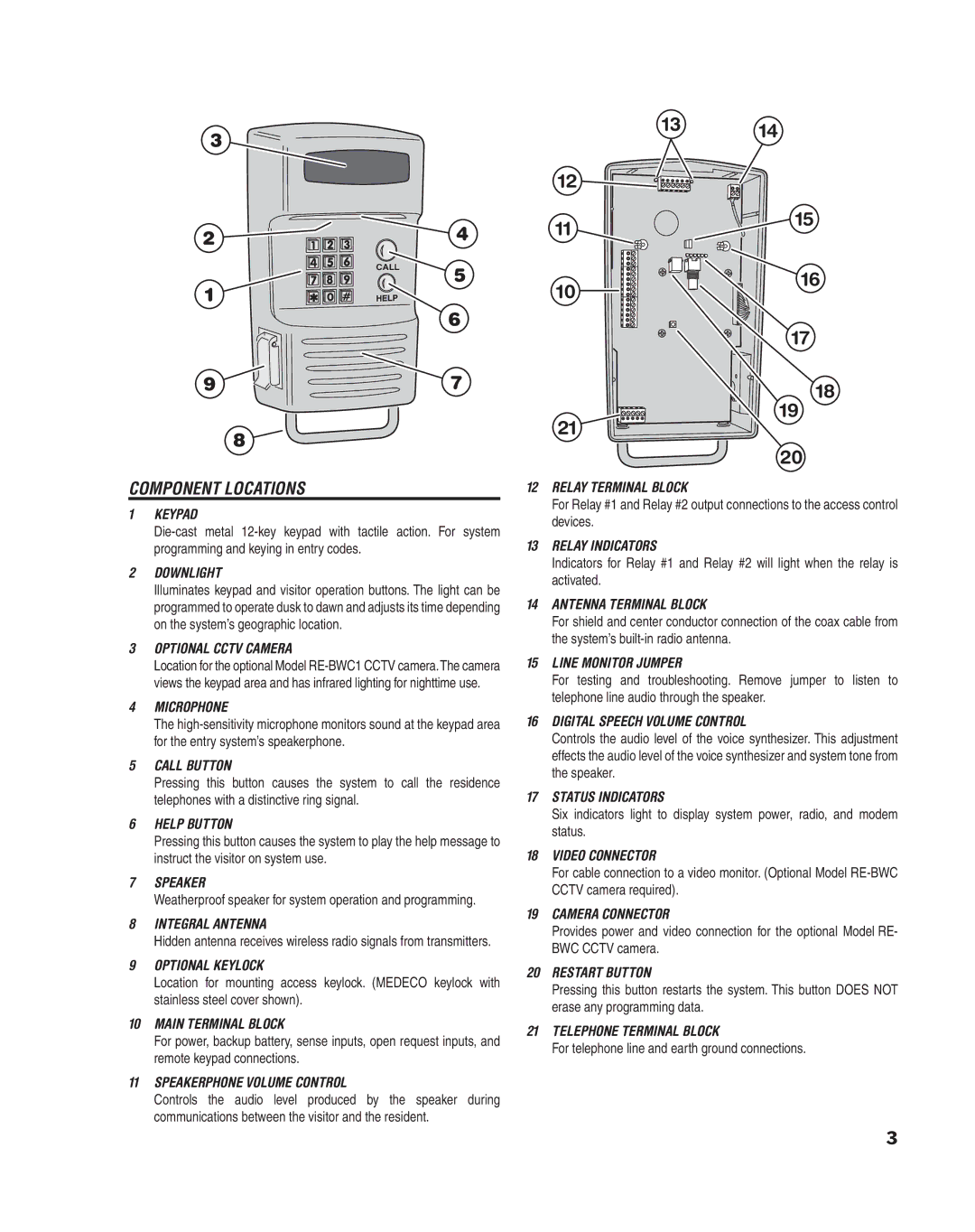
COMPONENT LOCATIONS
1KEYPAD
2DOWNLIGHT
Illuminates keypad and visitor operation buttons. The light can be programmed to operate dusk to dawn and adjusts its time depending on the system’s geographic location.
3OPTIONAL CCTV CAMERA
Location for the optional Model
4MICROPHONE
The
5CALL BUTTON
Pressing this button causes the system to call the residence telephones with a distinctive ring signal.
6HELP BUTTON
Pressing this button causes the system to play the help message to instruct the visitor on system use.
7SPEAKER
Weatherproof speaker for system operation and programming.
8INTEGRAL ANTENNA
Hidden antenna receives wireless radio signals from transmitters.
9OPTIONAL KEYLOCK
Location for mounting access keylock. (MEDECO keylock with stainless steel cover shown).
10MAIN TERMINAL BLOCK
For power, backup battery, sense inputs, open request inputs, and remote keypad connections.
11SPEAKERPHONE VOLUME CONTROL
Controls the audio level produced by the speaker during communications between the visitor and the resident.
17
18
19
21
20
12RELAY TERMINAL BLOCK
For Relay #1 and Relay #2 output connections to the access control devices.
13RELAY INDICATORS
Indicators for Relay #1 and Relay #2 will light when the relay is activated.
14ANTENNA TERMINAL BLOCK
For shield and center conductor connection of the coax cable from the system’s
15LINE MONITOR JUMPER
For testing and troubleshooting. Remove jumper to listen to telephone line audio through the speaker.
16DIGITAL SPEECH VOLUME CONTROL
Controls the audio level of the voice synthesizer. This adjustment effects the audio level of the voice synthesizer and system tone from the speaker.
17STATUS INDICATORS
Six indicators light to display system power, radio, and modem status.
18VIDEO CONNECTOR
For cable connection to a video monitor. (Optional Model
19CAMERA CONNECTOR
Provides power and video connection for the optional Model RE- BWC CCTV camera.
20RESTART BUTTON
Pressing this button restarts the system. This button DOES NOT erase any programming data.
21TELEPHONE TERMINAL BLOCK
For telephone line and earth ground connections.
3