POWER, BATTERY, & GROUND WIRING
Power Wiring
✦NOTE: DO NOT APPLY POWER UNTIL THE INSTALLATION IS COMPLETE.
1.Route two wires between the
•For power wire runs up to 100 feet, use 18 AWG, THHN
•For power wire runs up to 200 feet, use 16 AWG, THHN
2.Connect the wires to the transformer. Connect the other end of the wires to the two
Backup Battery
Use of battery backup is optional. It will allow the
TRANSFORMER
TRANSFORMER
BATTERY NEGATIVE
BATTERY POSITIVE
SENSE #1
OPEN #1
SENSE #2
OPEN #2
COMMON
KEYPAD CLK
KEYPAD DVAL
KEYPAD DAT 0
KEYPAD DAT 1
KEYPAD GND
KEYPAD PWR
TERMINALS
|
|
|
|
|
|
|
|
|
|
|
|
|
| 12 VOLT |
|
| 12 VOLT | ||||||||
1.2 AMP/HR |
| 1.2 AMP/HR | ||||||||||
| BATTERY |
|
| BATTERY | ||||||||
NOTE: BACKUP BATTERIES
WILL REQUIRE AN
EXTERNAL CHARGER
CASE
GROUND
|
|
|
|
|
|
|
|
|
|
|
|
|
|
|
|
|
|
|
| GROUND | |
|
|
|
|
|
|
|
|
| ||
|
|
|
|
|
|
|
|
| ||
| TIP RING |
| TIP RING |
| EARTH | |||||
|
|
| STAKE | |||||||
| HOUSE |
| TELCO |
|
|
|
|
|
|
|
|
|
|
|
|
|
|
|
|
|
|
TRANSFORMER
NOTE: TWO
RING | HOUSE |
|
TIP |
| |
|
| |
RING | TELEPHONE | |
TIP | HOUSE | |
RING |
| BYPASS |
MODULE | ||
TIP | TELCO | EARTH |
|
| |
RING |
| GROUND |
TELCO |
| |
TIP |
| |
|
| |
GROUND |
| |
STAKE |
| |
for the
Backup batteries will not fit into the
✦NOTE: Backup batteries are not required to maintain the
1.Route two wires between the RE-2 and the backup batteries.
2.Connect two 1.2 Amp/hour (minimum),
3.Connect the Battery #1 positive to the
4.Connect the Battery #2 negative to the
✦NOTE: The
Earth Ground
For the best ground, use size 12 gauge solid wire or larger to connect to an
1.Connect the wire from the earth ground to the rear case ground stud.
2.Connect the Telephone Bypass Module EARTH GROUND terminal to the earth ground wire.
3.Connect the
Case Ground
A ground wire connects the front and rear cases together. Be sure to
CONNECT INCOMING EARTH GROUND WIRE TO ONE
REAR CASE GROUND STUD WITH A RING TERMINAL
CONNECT THE FRONT |
| |
CASE GROUND WIRE |
| |
TO THE OTHER REAR | CONNECT THE | |
CASE GROUND STUD | ||
CIRCUIT BOARD | ||
| ||
| EARTH GROUND | |
| TERMINAL TO | |
IMPORTANT! FOR THE BEST PROTECTION AGAINST LIGHTNING DAMAGE | A CASE GROUND | |
STUD | ||
ALL EARTH GROUND CONNECTIONS MUST BE WIRED AS SHOWN | ||
|
Figure 15. Case Ground Connection
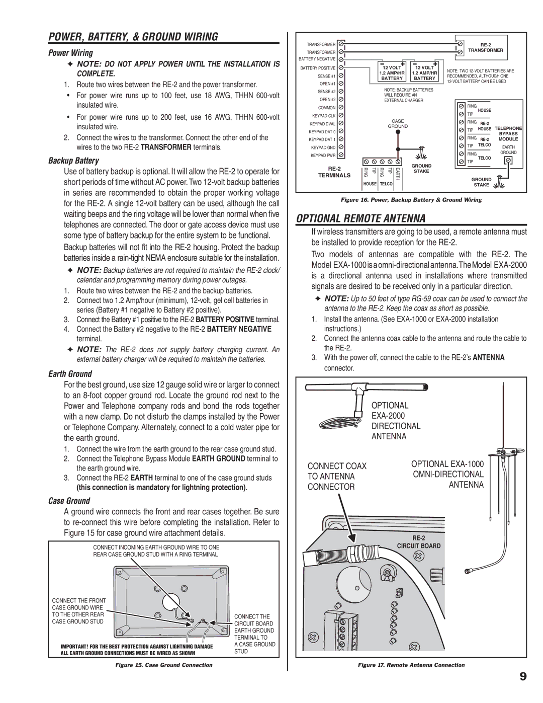
Figure 16. Power, Backup Battery & Ground Wiring
OPTIONAL REMOTE ANTENNA
If wireless transmitters are going to be used, a remote antenna must be installed to provide reception for the
Two models of antennas are compatible with the
✦NOTE: Up to 50 feet of type
1.Install the antenna. (See
2.Connect the antenna coax cable to the antenna and route the cable to the
3.With the power off, connect the cable to the
| OPTIONAL |
| |
| DIRECTIONAL |
| ANTENNA |
CONNECT COAX | OPTIONAL |
TO ANTENNA | |
CONNECTOR | ANTENNA |
| |
| CIRCUIT BOARD |
Figure 17. Remote Antenna Connection
9