OPTIONAL REMOTE KEYPAD
The optional Model
1.Mount the
2.Route
•For wire runs up to 300 feet use 24 AWG Belden Type 9931 or equivalent.
•For wire runs up to 600 feet use 20 AWG Weico Type 9405 or equivalent.
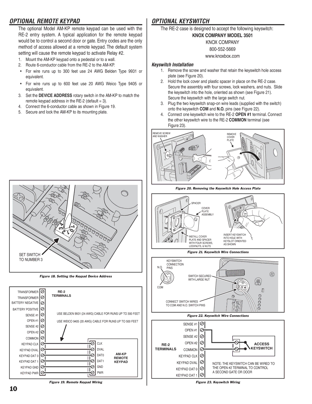
3.Set the DEVICE ADDRESS rotary switch in the
4.Connect the
5.Secure and lock the
OPTIONAL KEYSWITCH
The
KNOX COMPANY MODEL 3501
KNOX COMPANY
www.knoxbox.com
Keyswitch Installation
1.Remove the screw and washer that retain the keyswitch hole access plate (see Figure 20).
2.Hold the lock cover and plastic spacer in place on the
3.Plug the two keyswitch
4.Connect one keyswitch wire to the
REMOVE SCREW | REMOVE | |
AND WASHER | ||
COVER | ||
| ||
| PLATE |
Figure 20. Removing the Keyswitch Hole Access Plate
SPACER
COVER
PLATE
ASSEMBLY
INSTALL COVER
PLATE AND SPACER
WITH FOUR SCREWS,
LOCKNUTS, & NUTS
INSERT KEYSWITCH INTO HOLE WITH KEYSLOT ORIENTED AS SHOWN
SET SWITCH |
TO NUMBER 3 |
Figure 18. Setting the Keypad Device Address
Figure 21. Keyswitch Wire Connections
KEYSWITCH
CONNECTION
N.O. PINS
SWITCH SECURED
WITH LARGE NUT
COM
TRANSFORMER TRANSFORMER BATTERY NEGATIVE BATTERY POSITIVE SENSE #1 OPEN #1
TERMINALS
USE BELDEN 9931 (24 AWG) CABLE FOR RUNS UP TO 300 FEET
USE WEICO 9405 (20 AWG) CABLE FOR RUNS UP TO 500 FEET
CONNECT SWITCH WIRES
TO COM AND N.O. SWITCH PINS
Figure 22. Keyswitch Wire Connections
SENSE #2
OPEN #2
COMMON KEYPAD CLK KEYPAD DVAL KEYPAD DAT 0 KEYPAD DAT 1 KEYPAD GND KEYPAD PWR
CLK
DVAL
DAT0
REMOTE
DAT1 KEYPAD GND
PWR
SENSE #1
OPEN #1
SENSE #2
TERMINALS COMMON KEYPAD CLK KEYPAD DVAL KEYPAD DAT 0 KEYPAD DAT 1
ACCESS
KEYSWITCH
NOTE: THE KEYSWITCH CAN BE WIRED TO THE OPEN #2 TERMINAL TO CONTROL
A SECOND GATE OR DOOR
Figure 19. Remote Keypad Wiring
10