OPTIONAL COLOR CCTV CAMERA
Linear’s Model
The CAMERA connector is used to connect the camera to the
Camera Installation
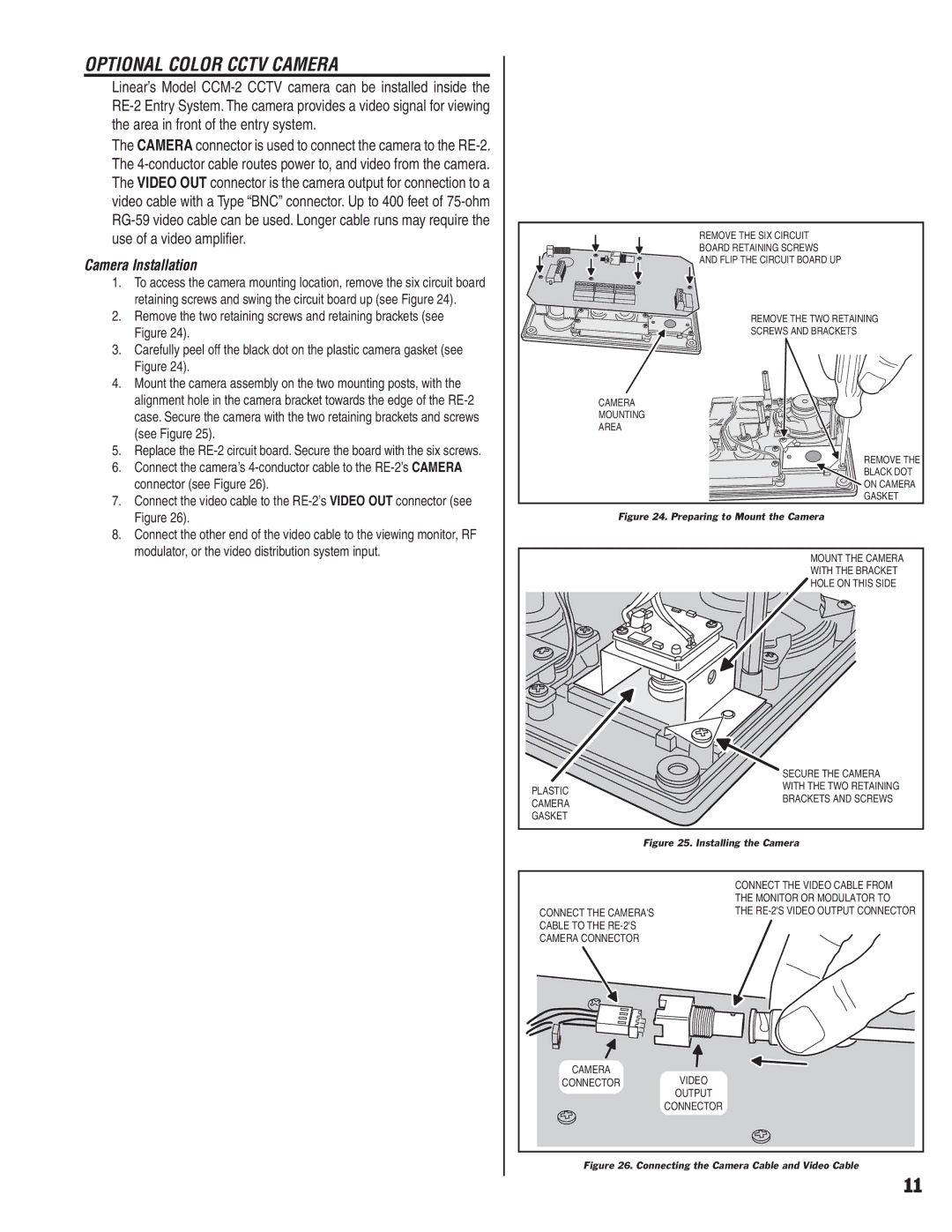
1.To access the camera mounting location, remove the six circuit board retaining screws and swing the circuit board up (see Figure 24).
2.Remove the two retaining screws and retaining brackets (see Figure 24).
3.Carefully peel off the black dot on the plastic camera gasket (see Figure 24).
4.Mount the camera assembly on the two mounting posts, with the alignment hole in the camera bracket towards the edge of the
5.Replace the
6.Connect the camera’s
7.Connect the video cable to the
8.Connect the other end of the video cable to the viewing monitor, RF modulator, or the video distribution system input.
REMOVE THE SIX CIRCUIT
BOARD RETAINING SCREWS
AND FLIP THE CIRCUIT BOARD UP
REMOVE THE TWO RETAINING
SCREWS AND BRACKETS
CAMERA
MOUNTING
AREA
REMOVE THE
BLACK DOT
ON CAMERA
GASKET
Figure 24. Preparing to Mount the Camera
MOUNT THE CAMERA
WITH THE BRACKET
HOLE ON THIS SIDE
| SECURE THE CAMERA | |
PLASTIC | WITH THE TWO RETAINING | |
BRACKETS AND SCREWS | ||
CAMERA | ||
| ||
GASKET |
|
Figure 25. Installing the Camera
CONNECT THE CAMERA'S CABLE TO THE
CAMERA
CONNECT THE VIDEO CABLE FROM THE MONITOR OR MODULATOR TO THE
CONNECTORVIDEO
OUTPUT
CONNECTOR
Figure 26. Connecting the Camera Cable and Video Cable
11