ENTRY SYSTEM MOUNTING
Pedestal Mounting
The
1.Open the
2.Use four security bolts and locking nuts to secure the backplate to the pedestal (see Figure 2).
Wall Mounting
The
1.Open the
2.Use the appropriate fasteners to secure the system’s backplate to the mounting surface. When mounting the system to a concrete wall, use concrete wedge anchors (see Figure 3).
REMOVE THE FOUR
SECURITY SCREWS
TO OPEN THE CASE
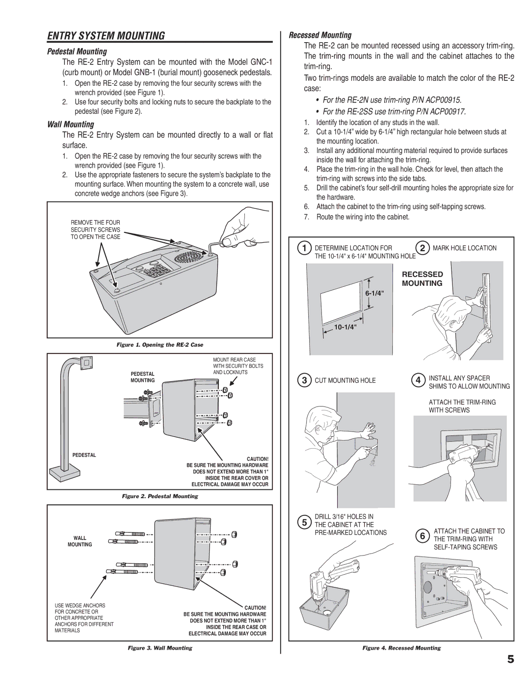
Figure 1. Opening the RE-2 Case
MOUNT REAR CASE
WITH SECURITY BOLTS
PEDESTALAND LOCKNUTS
MOUNTING
PEDESTAL
CAUTION! BE SURE THE MOUNTING HARDWARE DOES NOT EXTEND MORE THAN 1" INSIDE THE REAR COVER OR ELECTRICAL DAMAGE MAY OCCUR
Figure 2. Pedestal Mounting
Recessed Mounting
The
Two
•For the
•For the
1.Identify the location of any studs in the wall.
2.Cut a
3.Install any additional mounting material required to provide surfaces inside the wall for attaching the
4.Place the
5.Drill the cabinet’s four
6.Attach the cabinet to the
7.Route the wiring into the cabinet.
1 DETERMINE LOCATION FOR | 2 MARK HOLE LOCATION |
THE |
|
RECESSED
MOUNTING
10-1/4"
3 CUT MOUNTING HOLE | 4 INSTALL ANY SPACER |
| SHIMS TO ALLOW MOUNTING |
ATTACH THE
WITH SCREWS
DRILL 3/16" HOLES IN
5THE CABINET AT THE
WALL
MOUNTING
USE WEDGE ANCHORS FOR CONCRETE OR OTHER APPROPRIATE ANCHORS FOR DIFFERENT MATERIALS
CAUTION! BE SURE THE MOUNTING HARDWARE DOES NOT EXTEND MORE THAN 1" INSIDE THE REAR CASE OR ELECTRICAL DAMAGE MAY OCCUR
6 | ATTACH THE CABINET TO | |
| THE |
Figure 3. Wall Mounting
Figure 4. Recessed Mounting
5