TELEPHONE WIRING
The
Telephone Bypass Module
The
RE-2 MUST PASS THROUGH THE BYPASS MODULE.
The bypass module is housed in a
Telephone Wiring
•DO NOT ROUTE TELEPHONE AND AC WIRING INSIDE THE SAME CONDUIT. Route all telephone wires inside a dedicated conduit that is at least six inches away from any AC line wiring.
•All telephone wiring must be made on the “house” side of the telephone company’s demarcation device (the terminal block where the telephone line connects to the residence).
•If any security system or personal alert system at the residence is connected to the telephone line, be sure that it is connected to the line ahead of the Telephone Bypass Module using a
•Use only
Typical Telephone Wiring
1. Connect the bypass module’s EARTH GROUND terminal to a good |
earth ground. |
TELEPHONE WIRING OPTIONS
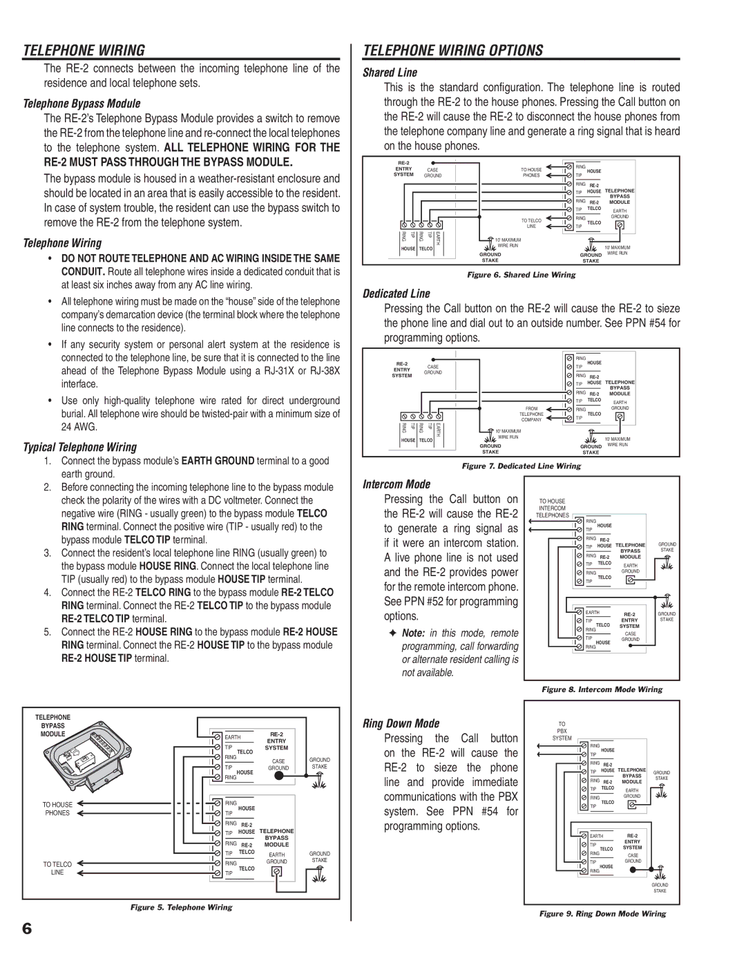
Shared Line
This is the standard confi guration. The telephone line is routed through the
|
|
|
|
| RING |
|
| |
ENTRY |
| CASE | TO HOUSE | HOUSE |
| |||
|
|
| ||||||
SYSTEM |
| GROUND | PHONES | TIP |
|
| ||
|
|
|
|
|
| RING | TELEPHONE | |
|
|
|
|
|
| TIP | HOUSE | |
|
|
|
|
|
| RING |
| BYPASS |
|
|
|
|
|
| MODULE | ||
|
|
|
|
|
| TIP | TELCO | EARTH |
|
|
|
|
|
|
|
| |
|
|
|
|
| TO TELCO | RING |
| GROUND |
|
|
|
|
| TELCO |
| ||
|
|
|
|
|
|
| ||
|
|
|
|
| LINE | TIP |
| |
|
|
|
|
|
|
| ||
RING | TIP | RING | TIP | EARTH | 10' MAXIMUM |
|
|
|
WIRE RUN |
|
| 10' MAXIMUM | |||||
HOUSE | TELCO |
|
|
| ||||
|
|
|
| |||||
|
|
|
|
| GROUND | GROUND | WIRE RUN | |
|
|
|
|
| STAKE | STAKE |
| |
Figure 6. Shared Line Wiring
Dedicated Line
Pressing the Call button on the
|
|
|
|
|
| RING | HOUSE |
|
|
| CASE |
| TIP |
| |||
ENTRY |
|
|
|
|
| |||
|
| GROUND |
|
|
|
| ||
SYSTEM |
|
| RING |
| ||||
|
|
|
| TELEPHONE | ||||
|
|
|
|
|
| TIP | HOUSE | |
|
|
|
|
|
| RING |
| BYPASS |
|
|
|
|
|
| MODULE | ||
|
|
|
|
|
| TIP | TELCO | EARTH |
|
|
|
|
| FROM | RING | TELCO | GROUND |
|
|
|
|
| TELEPHONE | TIP |
| |
|
|
|
|
| COMPANY |
|
| |
RING | TIP | RING | TIP | EARTH |
|
|
| |
10' MAXIMUM |
|
|
| |||||
WIRE RUN |
|
| 10' MAXIMUM | |||||
HOUSE | TELCO |
|
|
| ||||
|
|
|
| |||||
|
|
|
|
| GROUND | GROUND | WIRE RUN | |
|
|
|
|
| STAKE | STAKE |
| |
Figure 7. Dedicated Line Wiring
2. | Before connecting the incoming telephone line to the bypass module |
| check the polarity of the wires with a DC voltmeter. Connect the |
| negative wire (RING - usually green) to the bypass module TELCO |
| RING terminal. Connect the positive wire (TIP - usually red) to the |
| bypass module TELCO TIP terminal. |
3. | Connect the resident’s local telephone line RING (usually green) to |
| the bypass module HOUSE RING. Connect the local telephone line |
| TIP (usually red) to the bypass module HOUSE TIP terminal. |
4. | Connect the |
| RING terminal. Connect the |
|
|
5. | Connect the |
| RING terminal. Connect the |
|
Intercom Mode
Pressing the Call button on the
✦Note: in this mode, remote programming, call forwarding or alternate resident calling is not available.
TO HOUSE |
|
|
|
INTERCOM |
|
|
|
TELEPHONES |
|
|
|
RING | HOUSE |
|
|
TIP |
|
| |
|
|
| |
RING | TELEPHONE | GROUND | |
TIP | HOUSE | ||
RING |
| BYPASS | STAKE |
MODULE |
| ||
TIP | TELCO | EARTH |
|
|
|
| |
RING |
| GROUND |
|
TELCO |
|
| |
TIP |
|
| |
|
|
| |
EARTH | GROUND | ||
|
| ||
TIP | TELCO | ENTRY | STAKE |
RING | SYSTEM |
| |
| CASE |
| |
TIP |
|
| |
HOUSE | GROUND |
| |
RING |
|
| |
|
|
| |
Figure 8. Intercom Mode Wiring
TELEPHONE |
|
|
|
|
BYPASS |
|
|
|
|
MODULE | EARTH |
| ||
| ENTRY |
| ||
| TIP |
|
| |
| TELCO | SYSTEM |
| |
| RING |
|
| |
|
| CASE | GROUND | |
|
|
| ||
| TIP | HOUSE | GROUND | STAKE |
| RING |
|
| |
|
|
|
| |
TO HOUSE | RING | HOUSE |
|
|
PHONES | TIP |
|
| |
|
|
| ||
| RING | TELEPHONE |
| |
| TIP | HOUSE |
| |
| RING |
| BYPASS |
|
| MODULE |
| ||
| TIP | TELCO | EARTH | GROUND |
|
| |||
TO TELCO | RING |
| GROUND | STAKE |
TELCO |
|
| ||
LINE | TIP |
|
| |
|
|
| ||
Figure 5. Telephone Wiring
Ring Down Mode |
|
| ||
Pressing | the | Call | button | |
on the | ||||
to | sieze | the | phone | |
line | and | provide immediate | ||
communications with the PBX system. See PPN #54 for programming options.
TO |
|
|
| |
PBX |
|
|
| |
SYSTEM |
|
|
| |
RING | HOUSE |
|
| |
TIP |
|
| ||
|
|
| ||
RING | TELEPHONE |
| ||
TIP | HOUSE | GROUND | ||
| BYPASS | |||
RING |
| STAKE | ||
MODULE | ||||
| ||||
TIP | TELCO | EARTH |
| |
|
|
| ||
RING |
| GROUND |
| |
TELCO |
|
| ||
TIP |
|
| ||
|
|
| ||
EARTH |
| |||
TIP |
| ENTRY |
| |
TELCO | SYSTEM |
| ||
RING |
| |||
| CASE |
| ||
|
|
| ||
TIP | HOUSE | GROUND |
| |
RING |
|
| ||
|
|
| ||
|
|
| GROUND | |
|
|
| STAKE | |
6