Advanced Controller Programming
Entering Advanced Programming Mode |
| FUNCTION |
| OPTIONS |
| |||||
|
|
|
| |||||||
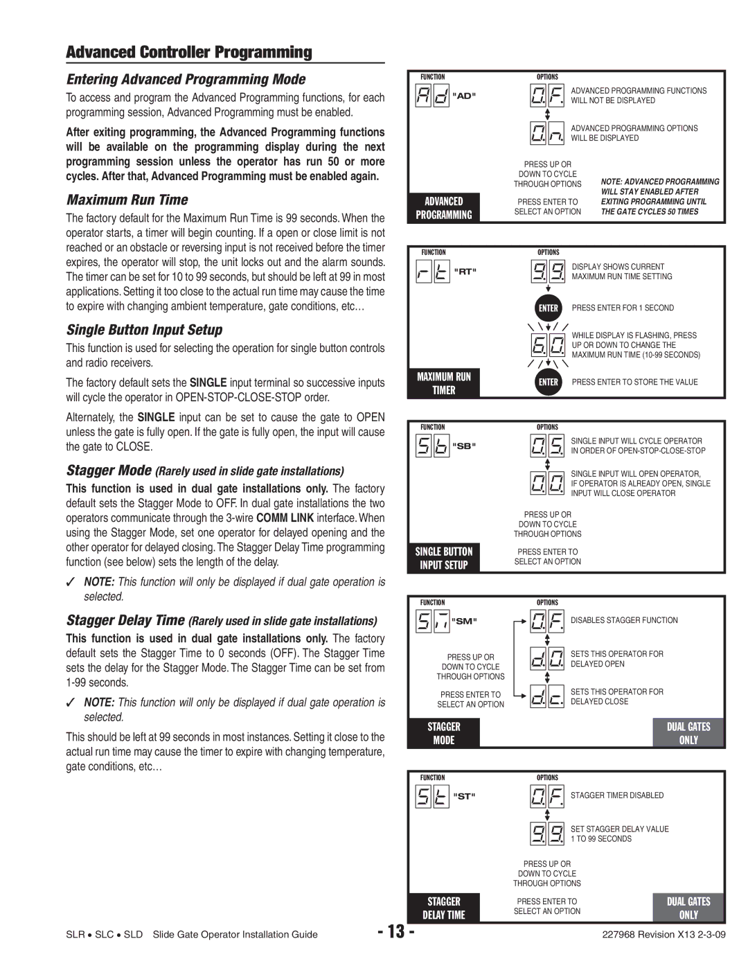
To access and program the Advanced Programming functions, for each |
|
|
|
| "AD" |
|
|
| ADVANCED PROGRAMMING FUNCTIONS | |
|
|
|
|
|
|
| ||||
|
|
|
|
|
|
| WILL NOT BE DISPLAYED | |||
programming session, Advanced Programming must be enabled. |
|
|
|
|
|
|
|
| ADVANCED PROGRAMMING OPTIONS | |
|
|
|
|
|
|
|
| |||
After exiting programming, the Advanced Programming functions |
|
|
|
|
|
|
|
| ||
|
|
|
|
|
|
|
| |||
|
|
|
|
|
|
|
| WILL BE DISPLAYED | ||
will be available on the programming display during the next |
|
|
|
|
|
|
|
| ||
|
|
|
|
|
|
|
|
|
| |
programming session unless the operator has run 50 or more |
|
|
|
|
| PRESS UP OR |
| |||
cycles. After that, Advanced Programming must be enabled again. |
|
|
|
|
| DOWN TO CYCLE | NOTE: ADVANCED PROGRAMMING | |||
|
|
|
|
|
| THROUGH OPTIONS | ||||
Maximum Run Time |
|
|
|
|
|
|
|
|
| WILL STAY ENABLED AFTER |
| ADVANCED | PRESS ENTER TO | EXITING PROGRAMMING UNTIL | |||||||
The factory default for the Maximum Run Time is 99 seconds. When the |
| PROGRAMMING | SELECT AN OPTION | THE GATE CYCLES 50 TIMES | ||||||
|
|
|
|
|
| |||||
operator starts, a timer will begin counting. If a open or close limit is not |
|
|
|
|
|
|
|
|
|
|
reached or an obstacle or reversing input is not received before the timer |
|
|
|
|
|
|
|
|
|
|
| FUNCTION |
| OPTIONS |
| ||||||
expires, the operator will stop, the unit locks out and the alarm sounds. |
|
|
| |||||||
|
|
|
| "RT" |
|
|
| DISPLAY SHOWS CURRENT | ||
|
|
|
|
|
|
| ||||
The timer can be set for 10 to 99 seconds, but should be left at 99 in most |
|
|
|
|
|
|
| |||
|
|
|
|
|
|
| MAXIMUM RUN TIME SETTING | |||
|
|
|
|
|
|
|
| |||
applications. Setting it too close to the actual run time may cause the time |
|
|
|
|
|
|
|
|
|
|
|
|
|
|
|
|
|
|
|
| |
|
|
|
|
|
|
|
|
|
| |
to expire with changing ambient temperature, gate conditions, etc… |
|
|
|
|
|
| ENTER PRESS ENTER FOR 1 SECOND | |||
Single Button Input Setup |
|
|
|
|
|
|
|
| WHILE DISPLAY IS FLASHING, PRESS | |
|
|
|
|
|
|
|
| |||
|
|
|
|
|
|
|
| |||
|
|
|
|
|
|
|
| |||
This function is used for selecting the operation for single button controls |
|
|
|
|
|
|
|
| UP OR DOWN TO CHANGE THE | |
|
|
|
|
|
|
|
| MAXIMUM RUN TIME | ||
and radio receivers. |
|
|
|
|
|
|
|
| ||
|
|
|
|
|
|
|
| |||
|
|
|
|
|
|
|
|
|
| |
|
|
|
|
|
|
|
|
|
| |
The factory default sets the SINGLE input terminal so successive inputs |
| MAXIMUM RUN |
| ENTER PRESS ENTER TO STORE THE VALUE | ||||||
|
| TIMER |
| |||||||
will cycle the operator in |
|
|
|
|
|
|
| |||
|
|
|
|
|
|
|
|
|
| |
Alternately, the SINGLE input can be set to cause the gate to OPEN |
|
|
|
|
|
|
|
|
|
|
unless the gate is fully open. If the gate is fully open, the input will cause |
| FUNCTION |
| OPTIONS |
| |||||
|
|
|
|
|
|
|
| SINGLE INPUT WILL CYCLE OPERATOR | ||
the gate to CLOSE. |
|
|
|
| "SB" |
|
|
| ||
|
|
|
|
|
|
| IN ORDER OF | |||
Stagger Mode (Rarely used in slide gate installations) |
|
|
|
|
|
|
|
| SINGLE INPUT WILL OPEN OPERATOR, | |
|
|
|
|
|
|
|
| |||
|
|
|
|
|
|
|
| |||
|
|
|
|
|
|
|
| |||
This function is used in dual gate installations only. The factory |
|
|
|
|
|
|
|
| IF OPERATOR IS ALREADY OPEN, SINGLE | |
|
|
|
|
|
|
|
| INPUT WILL CLOSE OPERATOR | ||
default sets the Stagger Mode to OFF. In dual gate installations the two |
|
|
|
|
|
|
|
| ||
|
|
|
|
| PRESS UP OR |
| ||||
operators communicate through the 3‑wire COMM LINK interface. When |
|
|
|
|
|
| ||||
|
|
|
|
| DOWN TO CYCLE |
| ||||
using the Stagger Mode, set one operator for delayed opening and the |
|
|
|
|
|
| ||||
|
|
|
|
| THROUGH OPTIONS |
| ||||
other operator for delayed closing. The Stagger Delay Time programming |
|
|
|
|
|
|
|
|
|
|
| SINGLE BUTTON | PRESS ENTER TO |
| |||||||
function (see below) sets the length of the delay. |
|
| ||||||||
| INPUT SETUP | SELECT AN OPTION |
| |||||||
|
|
|
|
|
|
| ||||
|
|
|
|
|
|
|
|
|
|
|
✓NOTE: This function will only be displayed if dual gate operation is
selected. |
|
|
|
|
|
|
|
|
|
|
|
|
|
|
|
| FUNCTION |
|
| OPTIONS |
| ||||||||
|
|
|
|
|
| |||||||||
Stagger Delay Time (Rarely used in slide gate installations) |
|
|
|
|
| "SM" |
|
|
|
| DISABLES STAGGER FUNCTION | |||
|
|
|
|
|
|
|
|
| ||||||
|
|
|
|
| ||||||||||
This function is used in dual gate installations only. The factory |
|
|
|
|
|
|
|
|
|
|
|
|
| |
|
|
|
|
|
|
|
|
|
|
|
| |||
default sets the Stagger Time to 0 seconds (OFF). The Stagger Time |
|
|
| PRESS UP OR |
|
|
|
| SETS THIS OPERATOR FOR |
| ||||
|
|
|
|
|
|
| ||||||||
sets the delay for the Stagger Mode. The Stagger Time can be set from |
|
|
| DOWN TO CYCLE |
|
|
|
| DELAYED OPEN |
| ||||
|
|
|
|
|
|
|
|
|
| |||||
|
|
|
| THROUGH OPTIONS |
|
|
|
| SETS THIS OPERATOR FOR |
| ||||
|
|
|
| PRESS ENTER TO |
|
|
|
|
| |||||
✓ NOTE: This function will only be displayed if dual gate operation is |
|
|
|
|
|
|
|
| ||||||
|
|
|
|
|
|
| DELAYED CLOSE |
| ||||||
|
|
| SELECT AN OPTION |
|
|
|
|
| ||||||
selected. |
|
|
|
|
|
|
|
|
|
|
|
|
|
|
|
| STAGGER |
|
|
|
|
|
|
| DUAL GATES | ||||
This should be left at 99 seconds in most instances. Setting it close to the |
|
|
|
|
|
|
|
| ||||||
|
| MODE |
|
|
|
|
|
|
| ONLY | ||||
actual run time may cause the timer to expire with changing temperature, |
|
|
|
|
|
|
|
|
|
|
|
|
| |
gate conditions, etc… |
|
|
|
|
|
|
|
|
|
|
|
|
|
|
|
|
| FUNCTION |
|
| OPTIONS |
| |||||||
|
|
|
|
|
| "ST" |
|
|
|
| STAGGER TIMER DISABLED |
| ||
|
|
|
|
|
|
|
|
|
|
| ||||
|
|
|
|
|
|
|
|
|
|
|
| SET STAGGER DELAY VALUE | ||
|
|
|
|
|
|
|
|
|
|
|
| |||
|
|
|
|
|
|
|
|
|
|
|
| |||
|
|
|
|
|
|
|
|
|
|
|
| |||
|
|
|
|
|
|
|
|
|
|
|
| 1 TO 99 SECONDS |
| |
|
|
|
|
|
|
|
|
|
|
|
|
| ||
|
|
|
|
|
|
|
| PRESS UP OR |
| |||||
|
|
|
|
|
|
|
| DOWN TO CYCLE |
| |||||
|
|
|
|
|
|
|
| THROUGH OPTIONS |
| |||||
|
|
|
|
|
|
|
|
| ||||||
|
|
| STAGGER |
| PRESS ENTER TO |
| DUAL GATES | |||||||
|
|
| DELAY TIME |
| SELECT AN OPTION |
| ONLY | |||||||
| - 13 |
|
|
|
|
|
|
|
| |||||
SLR • SLC • SLD Slide Gate Operator Installation Guide | - |
|
|
|
|
|
|
|
|
| 227968 Revision X13 | |||