000 - 260, 000 Btu/hr, 45 specifications
The Lochinvar 000 BTU/hr, 45,000 - 260 is a high-efficiency water heater designed for residential and commercial applications, showcasing advanced technologies that set it apart in the industry. With a powerful heating capacity of up to 260,000 BTU/hr, this unit is engineered to meet the varying demands of hot water for both large households and businesses.One of the standout features of the Lochinvar 000 is its innovative design that maximizes energy efficiency. Utilizing condensing technology, this water heater captures and reuses exhaust gases that would otherwise be lost, thereby improving thermal efficiency significantly. The result is an impressive Energy Factor (EF) rating that not only promotes sustainability but also translates into lower energy bills for the end user.
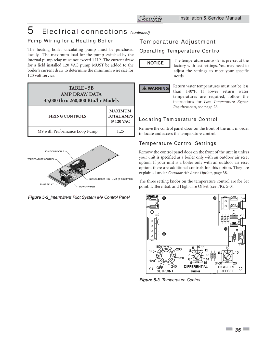
The unit is equipped with a user-friendly digital control interface that simplifies operation and monitoring. This control system allows for precise temperature adjustments, ensuring that users can maintain their desired water temperatures effortlessly. Additionally, the advanced diagnostics provided by the control system help in troubleshooting potential issues before they develop into more significant problems, enhancing the reliability of the unit.
Durability is another hallmark of the Lochinvar 000. Constructed with high-quality materials, including a robust stainless-steel tank, this water heater is designed to withstand the rigors of daily use. The stainless-steel construction also helps to resist corrosion, which is a common issue in water heaters, thereby extending the lifespan of the unit.
Furthermore, Lochinvar has integrated safety features into the design of the 000 model, including an automatic shut-off system and advanced flame safeguard controls to prevent hazardous situations. This focus on safety ensures peace of mind for users, making it an ideal choice for family homes and workplaces alike.
In terms of installation, the Lochinvar 000 is relatively straightforward, with options for both indoor and outdoor setups. The compact design allows for flexible installation, accommodating various space requirements without compromising performance.
Overall, the Lochinvar 000 BTU/hr, 45,000 - 260 combines reliability, efficiency, and advanced technology, making it a superior choice for those seeking a powerful and dependable water heating solution. This water heater not only meets but exceeds modern expectations for performance and safety, catering to a wide range of hot water needs.

