Installation & Service Manual
3Gas connections (continued)
TABLE - 3E
GAS PIPING SIZE CHART
Nominal |
|
|
|
| Length of Pipe in Straight Feet |
|
|
|
|
| Maximum | |||||
Iron Pipe |
|
|
|
|
|
|
|
|
| |||||||
Size |
|
|
|
|
|
|
|
|
|
|
|
|
|
|
| Capacity of Pipe |
|
|
|
|
|
|
|
|
|
|
|
|
|
|
| in Thousands of | |
Inches |
|
|
|
|
|
|
|
|
|
|
|
|
|
|
| |
10 | 20 | 30 | 40 | 50 | 60 | 70 | 80 | 90 |
| 100 | 125 | 150 | 175 | 200 | Btu/hr per hour | |
|
| |||||||||||||||
|
|
|
|
|
|
|
|
|
|
|
|
|
|
|
| for gas pressures |
3/4 | 369 | 256 | 205 | 174 | 155 | 141 | 128 | 121 | 113 |
| 106 | 95 | 86 | 79 | 74 | |
| of 13.5 Inches | |||||||||||||||
|
|
|
|
|
|
|
|
|
|
|
|
|
|
|
| |
1 | 697 | 477 | 384 | 328 | 292 | 267 | 246 | 226 | 210 |
| 200 | 179 | 164 | 149 | 138 | Water Column |
| (0.5 PSIG) or less | |||||||||||||||
|
|
|
|
|
|
|
|
|
|
|
|
|
|
|
| |
1 1/4 | 1,400 | 974 | 789 | 677 | 595 | 543 | 502 | 472 | 441 |
| 410 | 369 | 333 | 308 | 287 | and a pressure |
| drop of 0.5 Inch | |||||||||||||||
|
|
|
|
|
|
|
|
|
|
|
|
|
|
|
| |
1 1/2 | 2,150 | 1,500 | 1,210 | 1,020 | 923 | 830 | 769 | 707 | 666 |
| 636 | 564 | 513 | 472 | 441 | Water Column |
|
|
|
|
|
|
|
|
|
|
|
|
|
|
|
| (Based on NAT |
2 | 4,100 | 2,820 | 2,260 | 1,950 | 1,720 | 1,560 | 1,440 | 1,330 | 1,250 |
| 1,180 | 1,100 | 974 | 871 | 820 | |
| GAS, 1025 | |||||||||||||||
|
|
|
|
|
|
|
|
|
|
|
|
|
|
|
| Btu/hr per Cubic |
2 1/2 | 6,460 | 4,460 | 3,610 | 3,100 | 2,720 | 2,460 | 2,310 | 2,100 | 2,000 |
| 1,900 | 1,700 | 1,540 | 1,400 | 1,300 | |
| Foot of Gas and | |||||||||||||||
|
|
|
|
|
|
|
|
|
|
|
|
|
|
|
| |
|
|
|
|
|
|
|
|
|
|
|
|
|
|
|
| 0.60 Specific |
3 | 11,200 | 7,900 | 6,400 | 5,400 | 4,870 | 4,410 | 4,000 | 3,800 | 3,540 |
| 3,300 | 3,000 | 2,720 | 2,500 | 2,340 | |
| Gravity) | |||||||||||||||
|
|
|
|
|
|
|
|
|
|
|
|
|
|
|
| |
4 | 23,500 | 16,100 | 13,100 | 11,100 | 10,000 | 9,000 | 8,300 | 7,690 | 7,380 |
| 6,870 | 6,150 | 5,640 | 5,130 | 4,720 |
|
|
|
|
|
|
|
|
|
|
|
|
|
|
|
|
|
|
Gas Piping
GAS VALVE
GAS SHUTOFF VALVE
TRAP |
(DRIP LEG) |
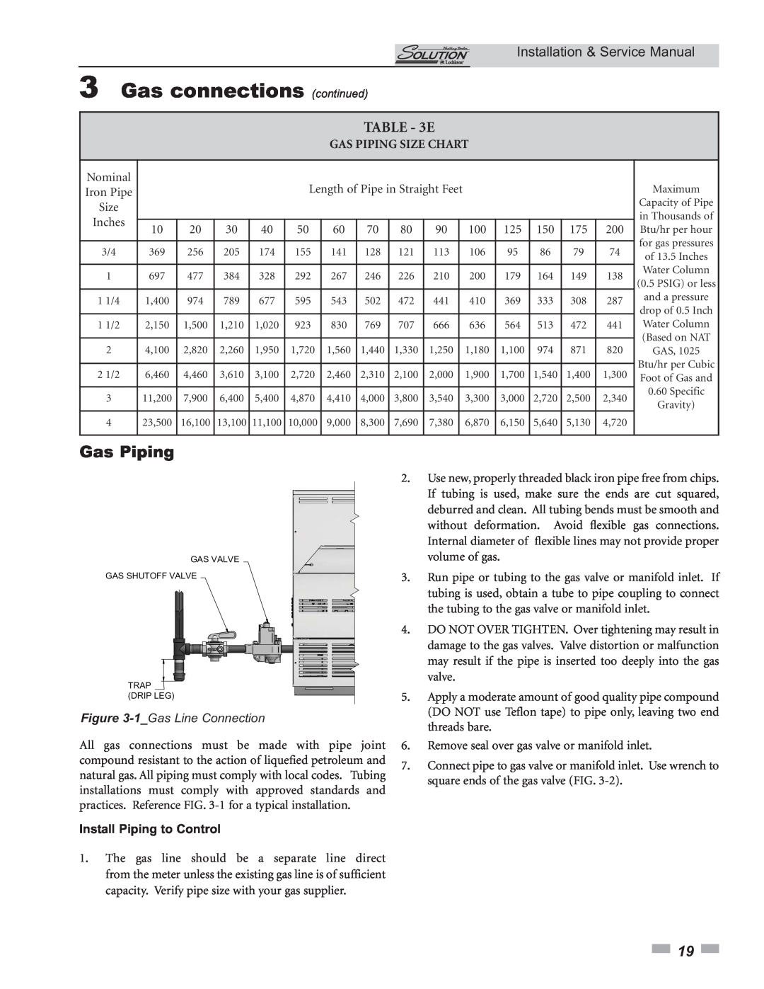
Figure 3-1_Gas Line Connection
All gas connections must be made with pipe joint compound resistant to the action of liquefied petroleum and natural gas. All piping must comply with local codes. Tubing installations must comply with approved standards and practices. Reference FIG.
1.The gas line should be a separate line direct from the meter unless the existing gas line is of sufficient capacity. Verify pipe size with your gas supplier.
2.Use new, properly threaded black iron pipe free from chips. If tubing is used, make sure the ends are cut squared, deburred and clean. All tubing bends must be smooth and without deformation. Avoid flexible gas connections. Internal diameter of flexible lines may not provide proper volume of gas.
3.Run pipe or tubing to the gas valve or manifold inlet. If tubing is used, obtain a tube to pipe coupling to connect the tubing to the gas valve or manifold inlet.
4.DO NOT OVER TIGHTEN. Over tightening may result in damage to the gas valves. Valve distortion or malfunction may result if the pipe is inserted too deeply into the gas valve.
5.Apply a moderate amount of good quality pipe compound (DO NOT use Teflon tape) to pipe only, leaving two end threads bare.
6.Remove seal over gas valve or manifold inlet.
7.Connect pipe to gas valve or manifold inlet. Use wrench to square ends of the gas valve (FIG.
![]() 19
19 ![]()