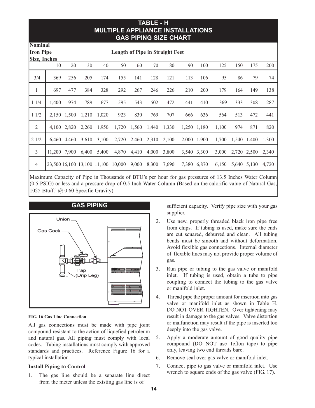
TABLE - H

MULTIPLE APPLIANCE INSTALLATIONS

GAS PIPING SIZE CHART


Nominal


Iron Pipe


Length of Pipe in Straight Feet


Size, Inches


10

20

30

40

50

60

70

80

90

100

125

150

175

200


3/4

369

256

205

174

155

141

128

121

113

106

95

86

79

74


1

697

477

384

328

292

267

246

226

210

200

179

164

149

138


1 1/4

1,400

974

789

677

595

543

502

472

441

410

369

333

308

287


1 1/2

2,150

1,500

1,210

1,020

923

830

769

707

666

636

564

513

472

441


2

4,100

2,820

2,260

1,950

1,720

1,560

1,440

1,330

1,250

1,180

1,100

974

871

820


2 1/2

6,460

4,460

3,610

3,100

2,720

2,460

2,310

2,100

2,000

1,900

1,700

1,540

1,400

1,300


3

11,200

7,900

6,400

5,400

4,870

4,410

4,000

3,800

3,540

3,300

3,000

2,720

2,500

2,340


4

23,500

16,100

13,100

11,100

10,000

9,000

8,300

7,690

7,380

6,870

6,150

5,640

5,130

4,720


Maximum Capacity of Pipe in Thousands of BTU’s per hour for gas pressures of 13.5 Inches Water Column (0.5 PSIG) or less and a pressure drop of 0.5 Inch Water Column (Based on the calorific value of Natural Gas, 1025 Btu/ft3 @ 0.60 Specific Gravity)

GAS PIPING

FIG. 16 Gas Line Connection

All gas connections must be made with pipe joint compound resistant to the action of liquefied petroleum and natural gas. All piping must comply with local codes. Tubing installations must comply with approved standards and practices. Reference Figure 16 for a typical installation.

Install Piping to Control

1.The gas line should be a separate line direct from the meter unless the existing gas line is of

sufficient capacity. Verify pipe size with your gas supplier.

2.Use new, properly threaded black iron pipe free from chips. If tubing is used, make sure the ends are cut squared, deburred and clean. All tubing bends must be smooth and without deformation. Avoid flexible gas connections. Internal diameter of flexible lines may not provide proper volume of gas.

3.Run pipe or tubing to the gas valve or manifold inlet. If tubing is used, obtain a tube to pipe coupling to connect the tubing to the gas valve or manifold inlet.

4.Thread pipe the proper amount for insertion into gas valve or manifold inlet as shown in Table H. DO NOT OVER TIGHTEN. Over tightening may result in damage to the gas valves. Valve distortion or malfunction may result if the pipe is inserted too deeply into the gas valve.

5.Apply a moderate amount of good quality pipe compound (DO NOT use Teflon tape) to pipe only, leaving two end threads bare.

6.Remove seal over gas valve or manifold inlet.

7.Connect pipe to gas valve or manifold inlet. Use wrench to square ends of the gas valve (FIG. 17).

14

Page 14
Image 14
Lochinvar 000 Btu/hr, CP-5M-4/08, 45, RSB-i&s-05, 000 - 500 warranty GAS Piping, Install Piping to Control

000 Btu/hr, 000 - 500, RSB-i&s-05, 45, CP-5M-4/08 specifications

The Lochinvar 000 BTU/hr, 45,000 - 260 is a high-efficiency water heater designed for residential and commercial applications, showcasing advanced technologies that set it apart in the industry. With a powerful heating capacity of up to 260,000 BTU/hr, this unit is engineered to meet the varying demands of hot water for both large households and businesses.

One of the standout features of the Lochinvar 000 is its innovative design that maximizes energy efficiency. Utilizing condensing technology, this water heater captures and reuses exhaust gases that would otherwise be lost, thereby improving thermal efficiency significantly. The result is an impressive Energy Factor (EF) rating that not only promotes sustainability but also translates into lower energy bills for the end user.

The unit is equipped with a user-friendly digital control interface that simplifies operation and monitoring. This control system allows for precise temperature adjustments, ensuring that users can maintain their desired water temperatures effortlessly. Additionally, the advanced diagnostics provided by the control system help in troubleshooting potential issues before they develop into more significant problems, enhancing the reliability of the unit.

Durability is another hallmark of the Lochinvar 000. Constructed with high-quality materials, including a robust stainless-steel tank, this water heater is designed to withstand the rigors of daily use. The stainless-steel construction also helps to resist corrosion, which is a common issue in water heaters, thereby extending the lifespan of the unit.

Furthermore, Lochinvar has integrated safety features into the design of the 000 model, including an automatic shut-off system and advanced flame safeguard controls to prevent hazardous situations. This focus on safety ensures peace of mind for users, making it an ideal choice for family homes and workplaces alike.

In terms of installation, the Lochinvar 000 is relatively straightforward, with options for both indoor and outdoor setups. The compact design allows for flexible installation, accommodating various space requirements without compromising performance.

Overall, the Lochinvar 000 BTU/hr, 45,000 - 260 combines reliability, efficiency, and advanced technology, making it a superior choice for those seeking a powerful and dependable water heating solution. This water heater not only meets but exceeds modern expectations for performance and safety, catering to a wide range of hot water needs.