■Test the Incoming Telephone Lines.
TEST: If you have a standard telephone with a modular cord, plug it into each jack of the network interface, or incoming telephone lines. If these jacks do not work you will require service by your local telephone company.
When the telephone lines were installed, the phone number should have been marked on the network interface jack. If that was not done, write the telephone number on the jack. You may require help from your local telephone company to decide which jack is for what number.
Some network interface jacks carry one line only, while some carry two. If your jacks are
■Connect Telephone Lines to Controller.
Remove from the controller box one line cord for each incoming telephone line. Additional cords and longer cords up to 25’ long may be purchased at a phone store or from your AT&T representative. LABEL EACH END OF EACH CORD WITH A LINE CORD LABEL.
If your interface jack is a
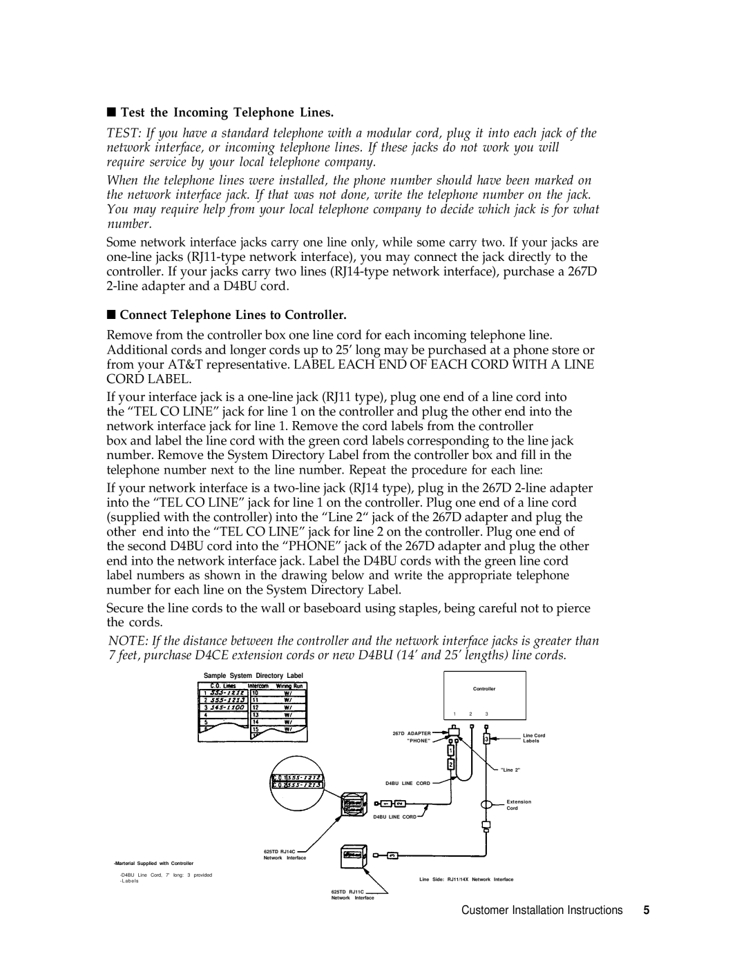
box and label the line cord with the green cord labels corresponding to the line jack number. Remove the System Directory Label from the controller box and fill in the telephone number next to the line number. Repeat the procedure for each line:
If your network interface is a
Secure the line cords to the wall or baseboard using staples, being careful not to pierce the cords.
NOTE: If the distance between the controller and the network interface jacks is greater than 7 feet, purchase D4CE extension cords or new D4BU (14’ and 25’ lengths) line cords.
Sample System Directory Label |
|
|
|
|
|
|
|
|
|
|
| Controller |
| ||
|
| 1 | 2 | 3 |
|
|
|
|
|
|
|
|
|
|
|
| 267D ADAPTER |
|
|
| Line Cord | ||
|
|
|
|
|
| ||
| "PHONE" |
|
|
| Labels | ||
|
|
|
|
| "Line 2" | ||
| D4BU LINE CORD |
|
|
|
|
| |
|
|
|
|
| Extension | ||
|
|
|
|
| Cord | ||
| D4BU LINE CORD |
|
|
|
|
| |
625TD RJ14C |
|
|
|
|
|
|
|
Network Interface |
|
|
|
|
|
|
|
|
|
|
|
|
|
| |
Line Side: RJ11/14X |
| Network Interface | |||||
- Labels |
| ||||||
|
|
|
|
|
|
| |
625TD RJ11C Network Interface
Customer Installation Instructions | 5 |