Step 1 Plan Your System
Draw a floor plan of your business, showing the location of the network interface jacks, where your local telephone lines come into the building. You will want to install your controller close to these jacks.
Show on the floor plan the location of each telephone in your system. Also show the distances of the cable run from the controller to each telephone location.
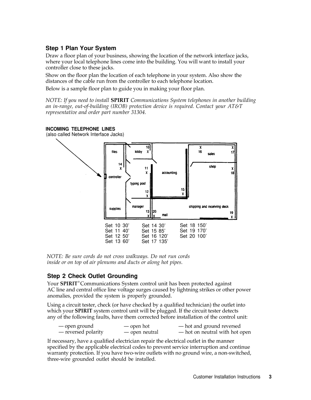
Below is a sample floor plan to guide you in making your floor plan.
NOTE: If you need to install SPIRIT Communications System telephones in another building an
INCOMING TELEPHONE LINES (also called Network Interface Jacks)
Set 10 | 30’ | Set 14 30’ | Set 18 | 150’ | |||
Set 11 | 40’ | Set 15 | 85’ | Set | 19 | 170’ | |
Set | 12 | 50’ | Set 16 | 120’ | Set | 20 | 100’ |
Set | 13 | 60’ | Set 17 | 135’ |
|
|
|
NOTE: Be sure cords do not cross walkways. Do not run cords inside or on top of air plenums and ducts or along hot pipes.
Step 2 Check Outlet Grounding
Your SPIRIT® Communications System control unit has been protected against
AC line and central office line voltage surges caused by lightning strikes or other power anomalies, provided the system is properly grounded.
Using a circuit tester, check (or have checked by a qualified technician) the outlet into which your SPIRIT system control unit will be plugged. If the circuit tester detects any of the following faults, have them corrected before installation of the control unit:
— open ground | — open hot | — hot and ground reversed |
— reversed polarity | — open neutral | — hot on neutral with hot open |
If necessary, have a qualified electrician repair the electrical outlet in the manner specified by the applicable electrical codes to prevent service interruption and continue warranty protection. If you have
Customer Installation Instructions | 3 |