Connecting the cables
Table
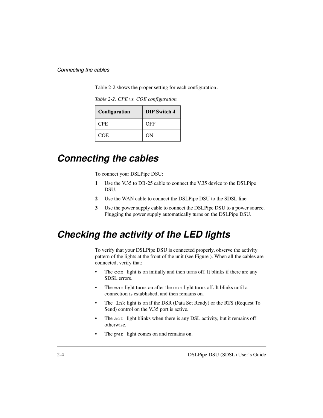
Table
Configuration
DIP Switch 4
CPE
OFF
COE
ON
Connecting the cables
To connect your DSLPipe DSU:
1Use the V.35 to
2Use the WAN cable to connect the DSLPipe DSU to the SDSL line.
3Use the power supply cable to connect the DSLPipe DSU to a power source. Plugging the power supply automatically turns on the DSLPipe DSU.
Checking the activity of the LED lights
To verify that your DSLPipe DSU is connected properly, observe the activity pattern of the lights at the front of the unit (see Figure ). When all the cables are connected, verify that:
•The con light is on initially and then turns off. It blinks if there are any SDSL errors.
•The wan light turns on after the con light turns off. It blinks until a connection is established, and then remains on.
•The lnk light is on if the DSR (Data Set Ready) or the RTS (Request To Send) control on the V.35 port is active.
•The act light blinks when there is any DSL activity, but it remains off otherwise.
•The pwr light comes on and remains on.
DSLPipe DSU (SDSL) User’s Guide |