Information Manual, Rev September
Introduction
Table of Contents
September USB-to-IEEE Bridge
Information Manual, Rev Evaluation Kit for USS-720
IOCTLSET1284REGISTER
USS-720 USB Device Driver Preliminary User Guide
IOCTL1284 Terminate
USS-720 USB Port Monitor Application Note
Evaluation Kit Contents
\SAMPLES
Hardware Requirements
Getting Started Instructions
OSR2.1 Cable Installation Instructions
Windows 98 Cable Installation Instructions
Software Updates
Port Creation
USB Driver and Port Monitor
Plug and Play
Eeprom
Lucent Technologies Inc
In-System Design, Inc
Lucent Technologies Microelectronics Group
USB Applications Support September
Introduction
Evaluation Kit Software
USS-720 Driver Software Object Code License Agreement
February
Ownership
USS-720 Software Use Agreement February
Licensed Software
Furnishing of Licensed Software
February Software Use Agreement
USS-720
04 Confidentiality
Warranty and Indemnity
Agreement Prevails
Nothing Construed
Integration
Publicity
Nonassignability
Addresses
Disputes
Applicable Law
Documentation
USS720.SYS
USS720.INF
USS-720 Software Use Agreement February
Application Note, Rev February
Software Components
Printer Enumeration
Customer-Defined Data
Plug and Play Operation PnP
USB Hardware Types Supported
Power Management
Installation Process
Operating Systems Supported
Print Types Supported
Printer Types Supported
Description
Features
Preliminary Data Sheet, Rev September
Table of Contents
USB-to-IEEE
Preliminary Data Sheet, Rev USS-720
Pin Information
Parallel Port nAck Signal Active-Low
Parallel Port nAutoFd Signal Active-Low
Parallel Port nSelectIn Signal Active-Low
Parallel Port nInit Signal Active-Low
Descriptor Locations
Overview
USB Port
Device Descriptor, Configurations, and Inter- faces
Device Descriptor Offset Field Size Value Description
USB-to- Ieee 1284 Bridge September
Onboard Device Descriptor
Configuration Descriptor
USB-to- Ieee
Bulk Out Endpoint Descriptor, I0A0E1
Interface Descriptors
Bulk In Endpoint Descriptor, I0A1E2
September USB-to-IEEE1284 Bridge
Bulk Out Endpoint Descriptor, I0A1E1
Interrupt Endpoint Descriptor, I0A2E3
Bulk Out Endpoint Descriptor, I0A2E1
Bulk In Endpoint Descriptor, I0A2E2
Standard Requests
Pipes
Requests
Get Port Status Data Bit Description
Printer Class-Specific Requests
SET1284REGISTER
Vendor-Specific Requests
GET1284REGISTER
Register-Based Operation
Ieee 1284 Port
Byte Register Data
Registers
GET1284REGISTER Data Byte Register Data
Interrupt Pipe Read Data
Parallel Port nFault Signal Reserved
Status Register Address Bit Symbol
Default Bit Symbol Bit Description
USB-to-IEEE1284 Bridge
Control Register Address Bit Symbol
Access Default Bit Symbol Bit Description
Parallel Port nInit Signal
USS-720Instant USB
ECP Command Register Address Bit Symbol Access
Mode20 Description
Extended Control Register Address Bit Symbol
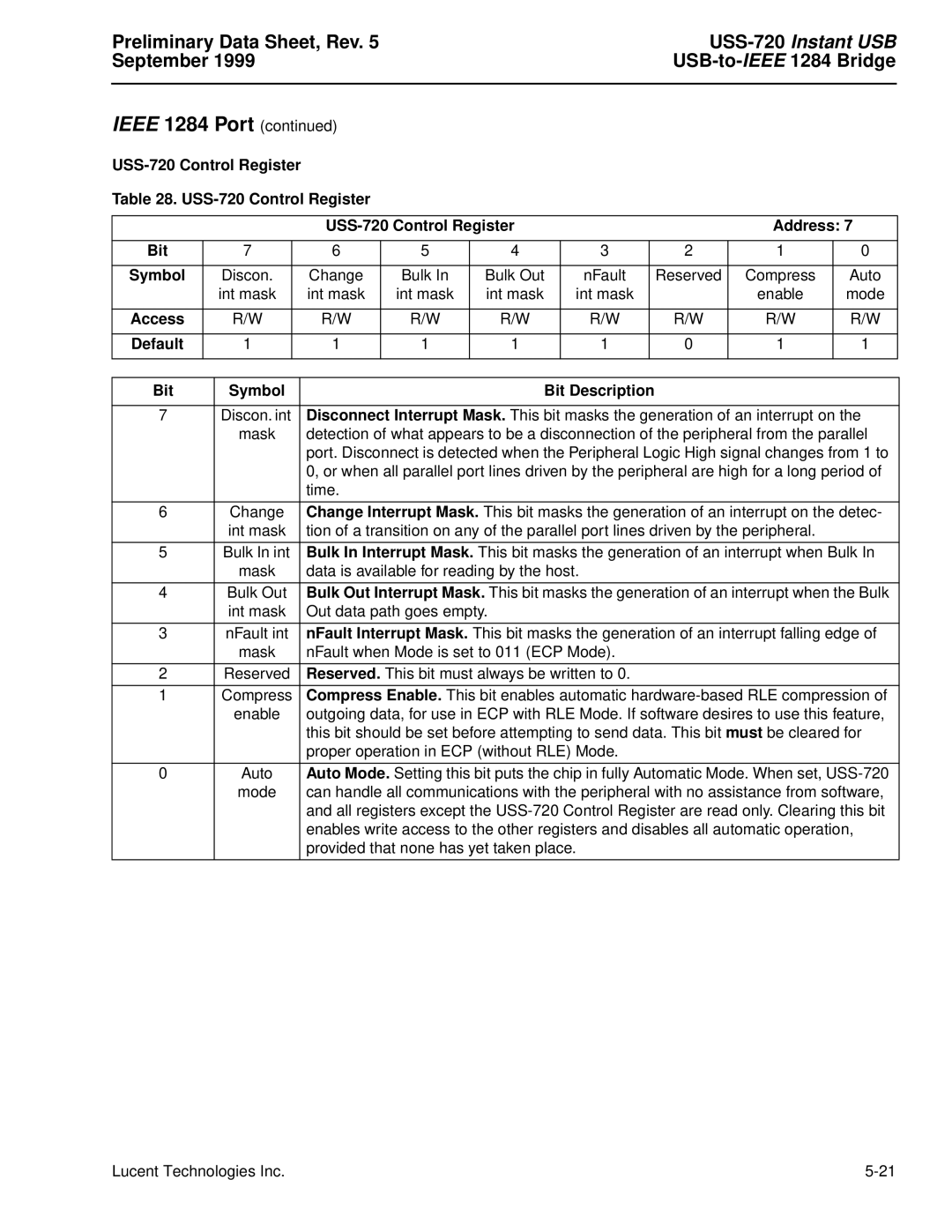
USS-720 Control Register Address Bit Symbol
USS-720 Setup Register Address Bit Symbol
Interrupts
External Crystal Connection
External Circuitry Requirements
Absolute Maximum Ratings Parameter Symbol Min Unit
Filter Bypass Mode
High Drive Mode
Self-Powered Mode
Clklo Clkhi
Electrical Characteristics
Parameter Symbol Test Conditions Min Typ Max Unit
Capacitance Values Parameter Unit
Output Delay Timing Parameter Min Max Unit
Timing Characteristics
Setup and Hold Input Timing Parameter
Device Code Package Comcode
Outline Diagram
Ordering Information
Pin Mqfp
Application Note February
Description
USS
Parallel
Port
Bridging USB to Typical Circuit Showing
Lucent Technologies Inc
Preliminary User Guide, Rev February
Signal Directions
IOCTL1284 Setmode
USB Device Driver
Initialization
O File Functions
Preliminary User Guide, Rev USS-720 February
CreateFile
ReadFile
Error Codes
WriteFile
DeviceIoControl
CloseHandle
Control Code Description
O Control Codes
Parameters
IOCTL1284 Ecpfwdtorev
IOCTL1284ECPREVTOFWD
IOCTL1284 Ecpsetchannel
IOCTL1284 Setmode
Register Mode Description
IOCTL1284 Terminate
Bulkinpipe
Ioctlabortpipe
Value Description
Bulkoutpipe
Ioctlcancelpiperequest
IOCTLGET1284REGISTER
ALTINTERFACE2
Ioctlgetaltsetting
ALTINTERFACE0
ALTINTERFACE1
Ioctlgetcapabilities
Ioctlgetconfigurationdescriptor
Ioctlgetdevicedescriptor
Ioctlgetdeviceinstances
Ioctlgetinterface
Bit Meaning
Ioctlgetportstatus
Command Description
IOCTLISSUEUSS720COMMAND
Byte Description
Ioctlreadinterruptpipe
Ioctlresetpipe
IOCTLSET1284REGISTER
Ioctlsetaltsetting
Ioctlsoftreset
Data Structure
O Control Data Structures
Deviceinstanceheader
Deviceinstance
REGISTER1284, *PREGISTER1284
REGISTER1284
ADVREGISTER1284, *PADVREGISTER1284
ADVREGISTER1284
Lucent Technologies Inc
USS-720 USB Port Monitor
Printer Cable with Instant USB
USS-720 Application Note USB Port Monitor February
Click on Enter Library
Software Installation Instructions
W98USS720EvalKit2402.zip to download the installation files
Application Note June
September MN99-052CMPR-1 Replaces MN97-061CMPR-04

