FFD 3.5" SCSI Flash Disk User Manual
6.Attach the SCSI cable to the host adapter and to the last device. Do not forget the device’s power connector.
7.Power ON the PC and verify that the host adapter recognizes the SCSI device.
8.If the SCSI device is recognized, power OFF the PC and install the next device. Verify recognition for the next device and then install. From this point on, the system should be up and running.
9.If you performed a BIOS uninstall procedure, or if the host adapter has no BIOS, the system will note recognize the devices until the drivers are installed.
8.2.2 Termination Configuration
When configuring termination, the basic rule to remember is termination is required at both ends of the SCSI chain.
•To install a new device as the last device on one of the sides of the complete cable, you must enable termination on the device.
•When replacing another device that was previously at the end of the cable and is now installed on another connector on the bus, you must disable termination on the device.
•When installing an external SCSI device in a system that has only internal devices, you must disable the host adapter’s termination using one of the following methods:
•Using software (as with the newer Adaptec).
•By removing the terminator packs (typically three) near the host adapter’s SCSI connector.
•By setting a jumper on the host adapter.
The situation is the same if you previously had only external devices.
8.2.3 SCSI ID Configuration
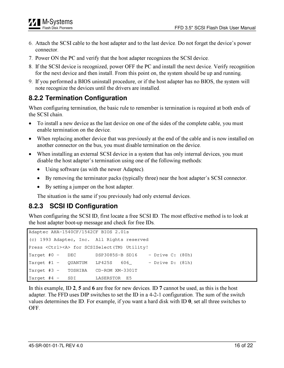
When configuring the SCSI ID, first locate a free SCSI ID. The most effective method is to look at the host adapter
Adaptec
(c)1993 Adaptec, Inc. All Rights reserved Press <Ctrl><A> for SCSISelect(TM) Utility!
Target #0 - | DEC | - | Drive | C: | (80h) | ||||
Target #1 - | QUANTUM | LP425S | 606_ | - | Drive | D: | (81h) | ||
Target | #3 | - | TOSHIBA |
|
|
|
| ||
Target | #4 | - | SDI | LASERSTOR | E5 |
|
|
|
|
In this example, ID 2, 5 and 6 are free for new devices. ID 7 cannot be used, as this is the host adapter. The FFD uses DIP switches to set the ID in a
16 of 22 |
