P 17/ 26
 Repair
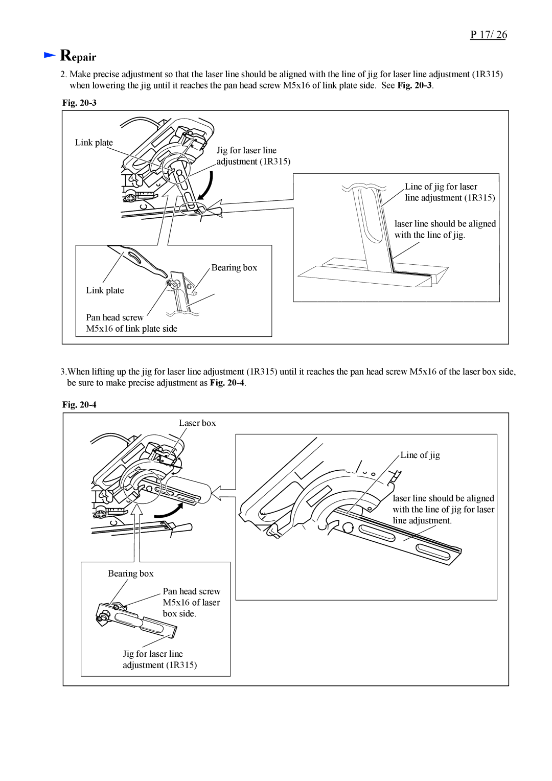
2.Make precise adjustment so that the laser line should be aligned with the line of jig for laser line adjustment (1R315) when lowering the jig until it reaches the pan head screw M5x16 of link plate side. See Fig.
Fig.
Link plate
Jig for laser line adjustment (1R315)
Line of jig for laser ![]() line adjustment (1R315)
line adjustment (1R315)
laser line should be aligned with the line of jig.
Bearing box
Link plate
Pan head screw
M5x16 of link plate side
3.When lifting up the jig for laser line adjustment (1R315) until it reaches the pan head screw M5x16 of the laser box side, be sure to make precise adjustment as Fig.
Fig.
Laser box
Line of jig
laser line should be aligned with the line of jig for laser line adjustment.
Bearing box
Pan head screw ![]()
![]() M5x16 of laser
M5x16 of laser ![]() box side.
box side.
Jig for laser line adjustment (1R315)