P 6 / 26
 Repair
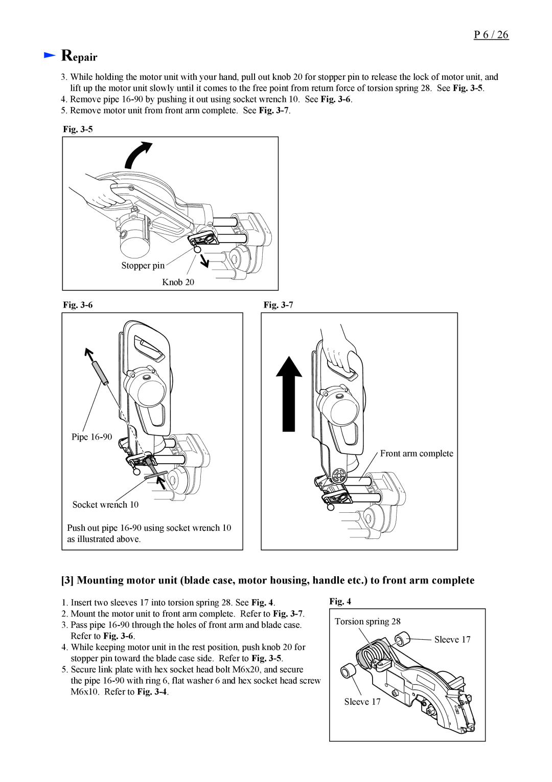
3.While holding the motor unit with your hand, pull out knob 20 for stopper pin to release the lock of motor unit, and lift up the motor unit slowly until it comes to the free point from return force of torsion spring 28. See Fig.
4.Remove pipe
5.Remove motor unit from front arm complete. See Fig.
Fig. |
|
| Stopper pin |
| Knob 20 |
Fig. | Fig. |
Pipe
Socket wrench 10
Push out pipe
Front arm complete
[3] Mounting motor unit (blade case, motor housing, handle etc.) to front arm complete
1.Insert two sleeves 17 into torsion spring 28. See Fig. 4.
2.Mount the motor unit to front arm complete. Refer to Fig.
3.Pass pipe
4.While keeping motor unit in the rest position, push knob 20 for stopper pin toward the blade case side. Refer to Fig.
5.Secure link plate with hex socket head bolt M6x20, and secure
the pipe
Fig. 4
Torsion spring 28 |
Sleeve 17 |
Sleeve 17 |