P 7/ 27
 Repair
[3] DISASSEMBLY/ASSEMBLY
[3]-2. Armature, Motor bracket complete (cont.)
DISASSEMBLING
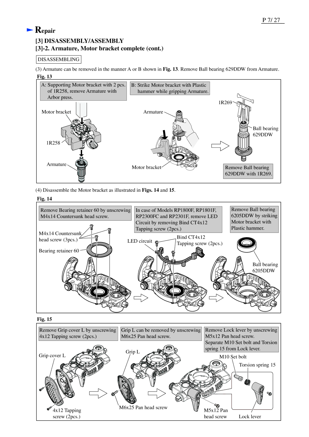
(3)Armature can be removed in the manner A or B shown in Fig. 13. Remove Ball bearing 629DDW from Armature.
Fig. 13
A:Supporting Motor bracket with 2 pcs. of 1R258, remove Armature with Arbor press.
Motor bracket
1R258 ![]()
![]()
![]()
![]()
B:Strike Motor bracket with Plastic hammer while gripping Armature.
1R269![]()
![]()
![]()
![]()
![]()
![]()
Armature
![]() Ball bearing
Ball bearing ![]()
![]()
![]()
![]()
![]()
![]()
![]() 629DDW
629DDW
Armature | Motor bracket |
|
Remove Ball bearing 629DDW with 1R269.
(4)Disassemble the Motor bracket as illustrated in Figs. 14 and 15.
Fig. 14
Remove Bearing retainer 60 by unscrewing In case of Models RP1800F, RP1801F, | |||
M4x14 Countersunk head screw. | RP2300FC and RP2301F, remove LED | ||
| Circuit by removing Bind CT4x12 | ||
M4x14 Countersunk | Tapping screw (2pcs.) | ||
| Bind CT4x12 | ||
head screw (3pcs.) | LED circuit | ||
Tapping screw (2pcs.) | |||
|
| ||
Bearing retainer 60 |
|
| |
Remove Ball bearing 6205DDW by striking Motor bracket with Plastic hammer.
Ball bearing 6205DDW
Fig. 15
Remove Grip cover L by unscrewing 4x12 Tapping screw (2pcs.)
Grip cover L
![]() 4x12 Tapping screw (2pcs.)
4x12 Tapping screw (2pcs.)
Grip L can be removed by unscrewing | Remove Lock lever by unscrewing | ||
M6x25 Pan head screw. | M5x12 Pan head screw. | ||
| Separate M10 Set bolt and Torsion | ||
Grip L | spring 15 from Lock lever. | ||
M10 Set bolt | |||
| |||
|
| Torsion spring 15 | |
M6x25 Pan head screw | M5x12 Pan |
| |
|
| ||
| head screw | Lock lever | |
