P 21/ 27
 Wiring diagram
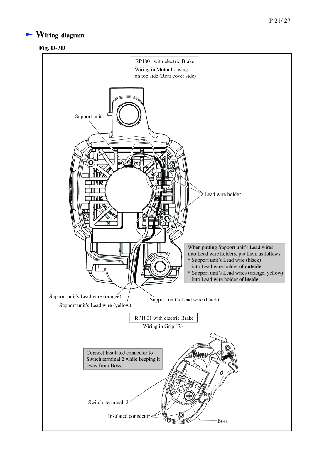
Fig. D-3D
RP1801 with electric Brake
Wiring in Motor housing
on top side (Rear cover side)
Support unit
![]() Lead wire holder
Lead wire holder
| When putting Support unit’s Lead wires | |
| into Lead wire holders, put them as follows. | |
| * Support unit’s Lead wire (black) | |
| into Lead wire holder of outside | |
| * Support unit’s Lead wires (orange, yellow) | |
| into Lead wire holder of inside | |
Support unit’s Lead wire (orange) | Support unit’s Lead wire (black) | |
Support unit’s Lead wire (yellow) | ||
|
RP1801 with electric Brake
Wiring in Grip (R)
Connect Insulated connector to Switch terminal 2 while keeping it away from Boss.
Switch terminal 2
Insulated connector
Boss