P 5/ 27
 Repair
[3]DISASSEMBLY/ASSEMBLY
[3]-1. Base complete
ASSEMBLING
Take the disassembling step in reverse.
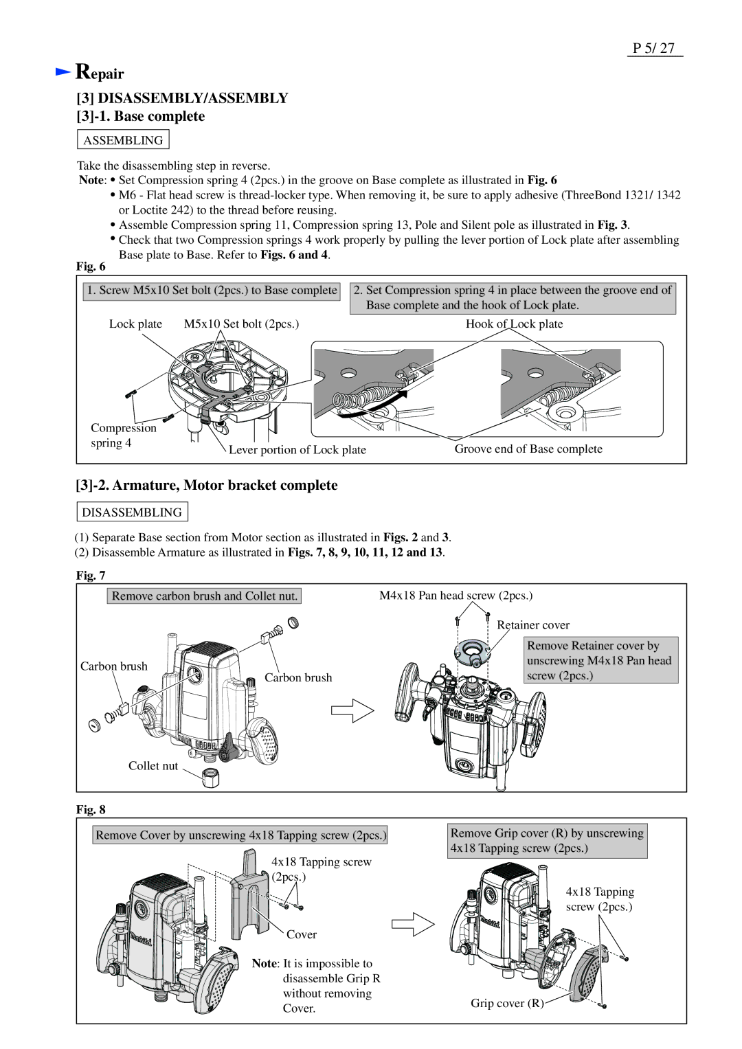
Note: ![]() Set Compression spring 4 (2pcs.) in the groove on Base complete as illustrated in Fig. 6
Set Compression spring 4 (2pcs.) in the groove on Base complete as illustrated in Fig. 6
![]() M6 - Flat head screw is
M6 - Flat head screw is
![]() Assemble Compression spring 11, Compression spring 13, Pole and Silent pole as illustrated in Fig. 3.
Assemble Compression spring 11, Compression spring 13, Pole and Silent pole as illustrated in Fig. 3.
![]() Check that two Compression springs 4 work properly by pulling the lever portion of Lock plate after assembling Base plate to Base. Refer to Figs. 6 and 4.
Check that two Compression springs 4 work properly by pulling the lever portion of Lock plate after assembling Base plate to Base. Refer to Figs. 6 and 4.
Fig. 6
1. Screw M5x10 Set bolt (2pcs.) to Base complete
Lock plate | M5x10 Set bolt (2pcs.) |
2.Set Compression spring 4 in place between the groove end of Base complete and the hook of Lock plate.
Hook of Lock plate
Compression |
|
|
spring 4 | Lever portion of Lock plate | Groove end of Base complete |
|
[3]-2. Armature, Motor bracket complete
DISASSEMBLING
(1)Separate Base section from Motor section as illustrated in Figs. 2 and 3.
(2)Disassemble Armature as illustrated in Figs. 7, 8, 9, 10, 11, 12 and 13.
Fig. 7
Remove carbon brush and Collet nut.
Carbon brush
Carbon brush
M4x18 Pan head screw (2pcs.)
Retainer cover
Remove Retainer cover by unscrewing M4x18 Pan head screw (2pcs.)
Collet nut
Fig. 8
Remove Cover by unscrewing 4x18 Tapping screw (2pcs.)
4x18 Tapping screw (2pcs.)
![]() Cover
Cover
Note: It is impossible to disassemble Grip R without removing Cover.
Remove Grip cover (R) by unscrewing 4x18 Tapping screw (2pcs.)
4x18 Tapping screw (2pcs.)
Grip cover (R)![]()
