P 14/ 27
 Wiring diagram
Fig. D-2B
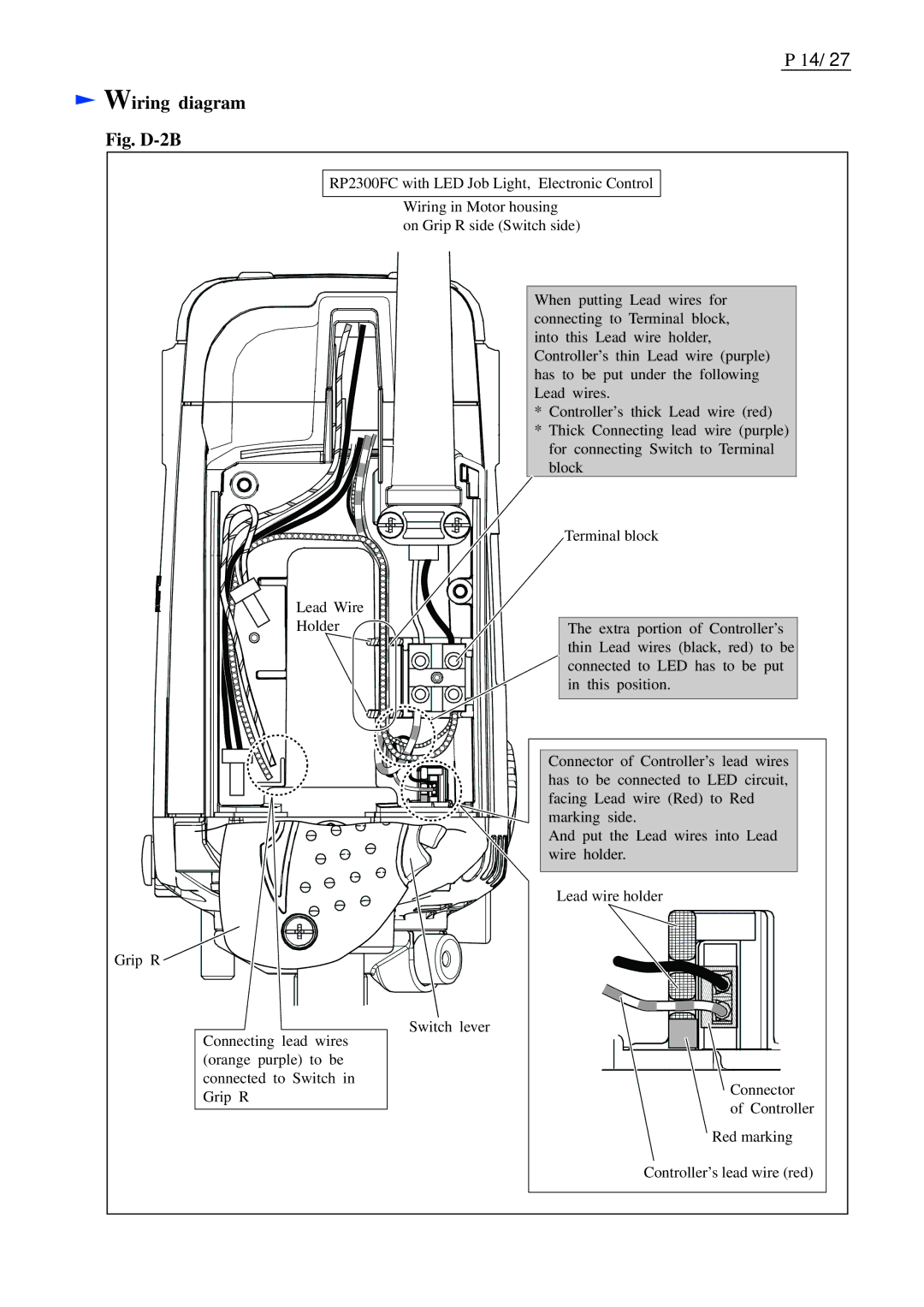
RP2300FC with LED Job Light, Electronic Control
Wiring in Motor housing on Grip R side (Switch side)
When putting Lead wires for connecting to Terminal block, into this Lead wire holder, Controller’s thin Lead wire (purple) has to be put under the following Lead wires.
* Controller’s thick Lead wire (red)
* Thick Connecting lead wire (purple)
for connecting Switch to Terminal block
Lead Wire Holder
Terminal block
The extra portion of Controller’s thin Lead wires (black, red) to be connected to LED has to be put in this position.
Connector of Controller’s lead wires has to be connected to LED circuit, facing Lead wire (Red) to Red marking side.
And put the Lead wires into Lead wire holder.
Lead wire holder
Grip R ![]()
Connecting lead wires | Switch lever | |
| ||
(orange purple) to be |
| |
connected to Switch in | Connector | |
Grip R | ||
of Controller | ||
| ||
| Red marking |
Controller’s lead wire (red)