P 20/ 27
 Wiring diagram
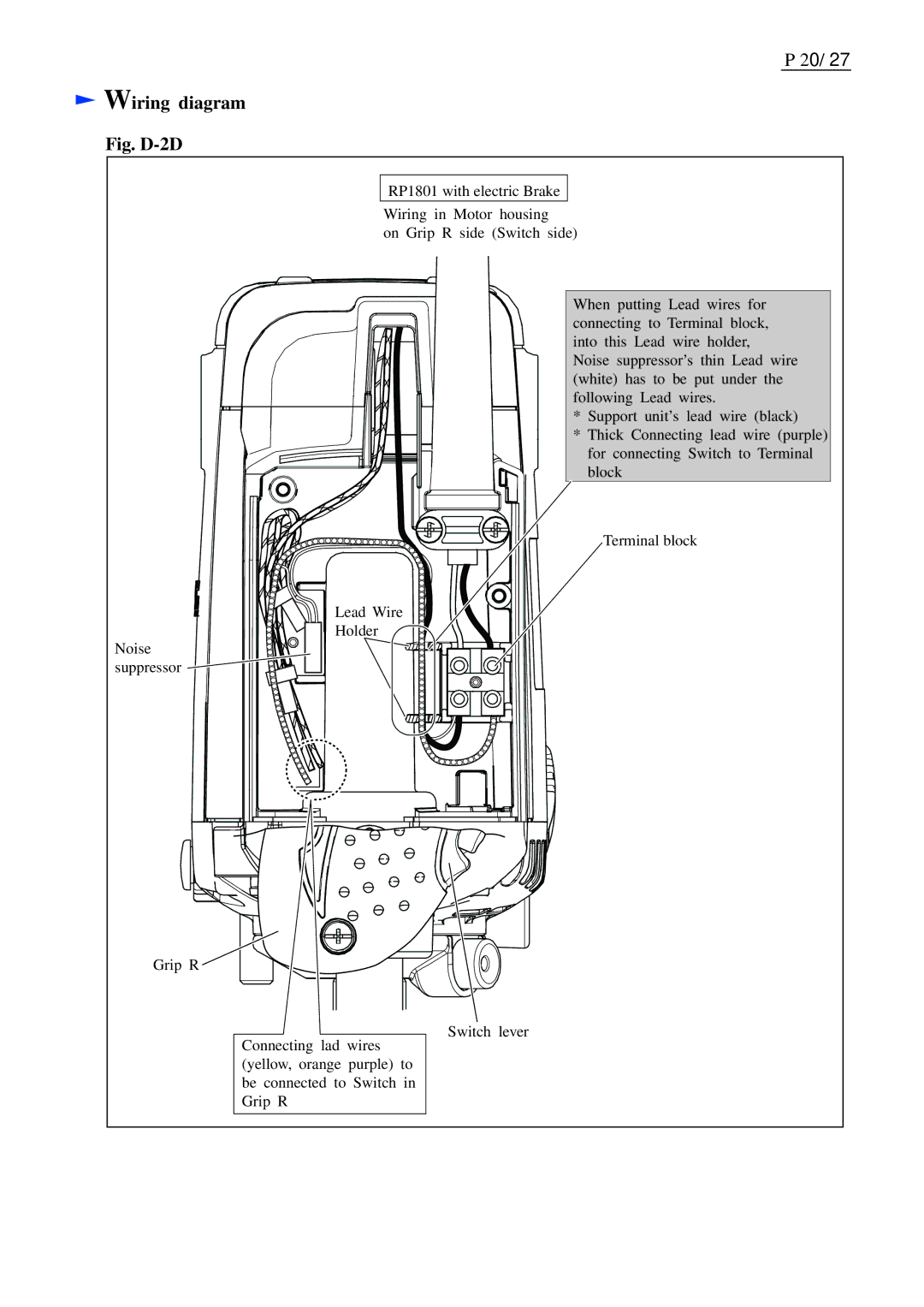
Fig. D-2D
RP1801 with electric Brake
Wiring in Motor housing
on Grip R side (Switch side)
Lead Wire
Holder
Noise![]() suppressor
suppressor ![]()
Grip R ![]()
Connecting lad wires (yellow, orange purple) to be connected to Switch in Grip R
When putting Lead wires for connecting to Terminal block, into this Lead wire holder, Noise suppressor’s thin Lead wire (white) has to be put under the following Lead wires.
*Support unit’s lead wire (black)
*Thick Connecting lead wire (purple) for connecting Switch to Terminal block
Terminal block
Switch lever