P 8/ 27
 Repair
[3] DISASSEMBLY/ASSEMBLY
[3]-2. Armature, Motor bracket complete
ASSEMBLING
(1)Assemble Ball bearing 6205DDW to Motor bracket. Refer to the right illustration in Fig. 14.
(2)In case of RP1800F, RP1801F, RP2300FC and RP2301FC, secure LED circuit with 4x12 Tapping screw (2pcs.). Refer to the center illustration in Fig. 14.
(3)Tighten Bearing retainer 60 with M4x14 Countersunk head screw (3pcs.) to secure Ball bearing 6205DDW. Refer to the left illustration in Fig. 14.
Note: Apply adhesive ThreeBond 1321 / 1342 or Loctite 242 to the threaded portion of M4x14 Countersunk head screw (3pcs.)
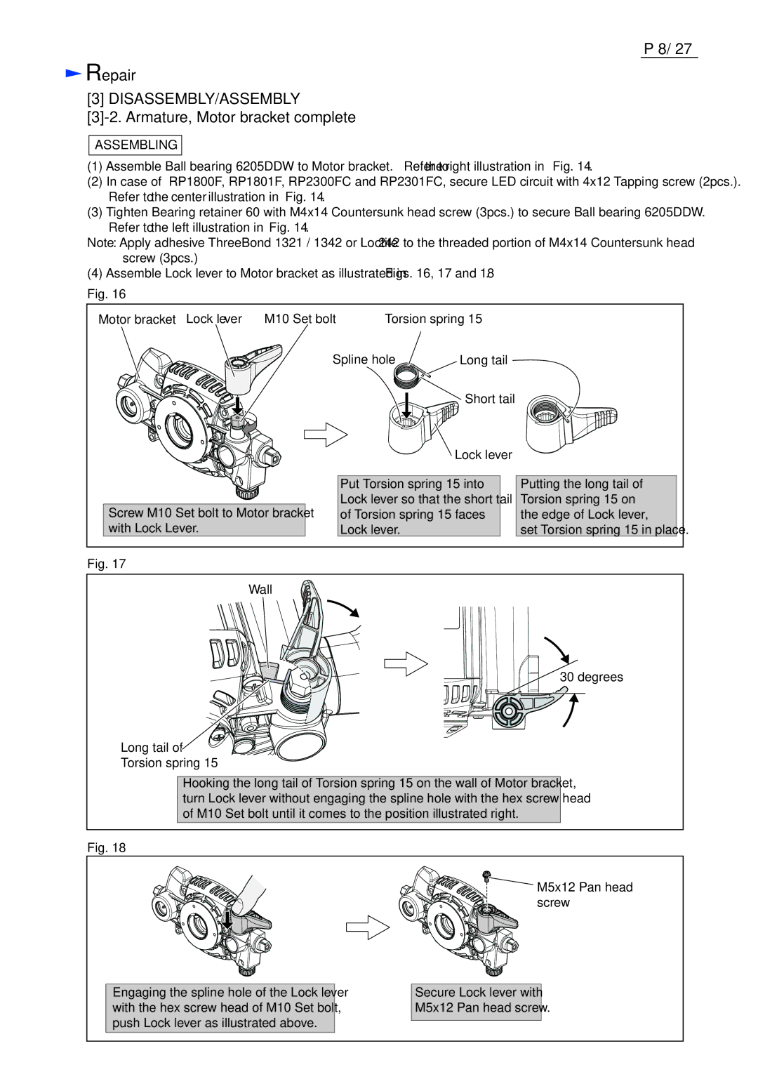
(4)Assemble Lock lever to Motor bracket as illustrated in Figs. 16, 17 and 18.
Fig. 16
Motor bracket Lock lever | M10 Set bolt | Torsion spring 15 |
Screw M10 Set bolt to Motor bracket with Lock Lever.
Spline hole | Long tail |
|
| Short tail |
|
| Lock lever |
|
Put Torsion spring 15 into | Putting the long tail of | |
Lock lever so that the short tail | Torsion spring 15 on | |
of Torsion spring 15 faces | the edge of Lock lever, | |
Lock lever. |
| set Torsion spring 15 in place. |
Fig. 17
Wall
30 degrees
Long tail of ![]() Torsion spring 15
Torsion spring 15
Hooking the long tail of Torsion spring 15 on the wall of Motor bracket, turn Lock lever without engaging the spline hole with the hex screw head of M10 Set bolt until it comes to the position illustrated right.
Fig. 18
Engaging the spline hole of the Lock lever with the hex screw head of M10 Set bolt, push Lock lever as illustrated above.
![]() M5x12 Pan head screw
M5x12 Pan head screw
Secure Lock lever with
M5x12 Pan head screw.