P 4/ 27
 Repair
[3]DISASSEMBLY/ASSEMBLY [3]-1. Base complete (cont.)
DISASSEMBLING
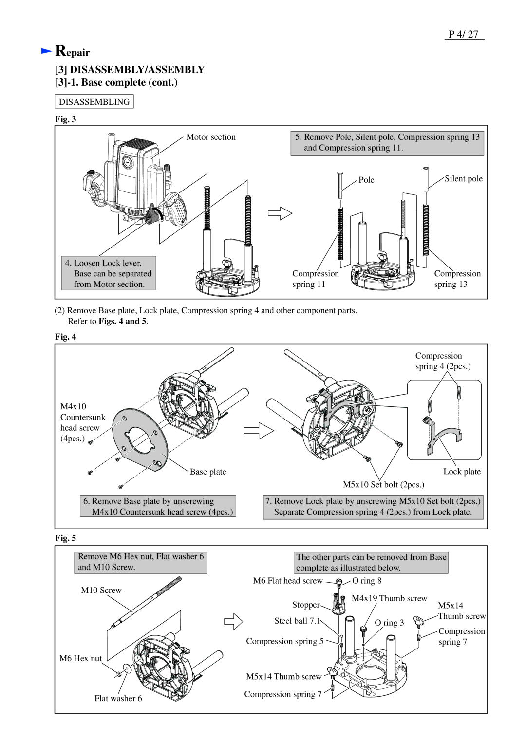
Fig. 3
Motor section
5.Remove Pole, Silent pole, Compression spring 13 and Compression spring 11.
Pole | Silent pole |
4.Loosen Lock lever. Base can be separated from Motor section.
Compression | Compression |
spring 11 | spring 13 |
(2)Remove Base plate, Lock plate, Compression spring 4 and other component parts. Refer to Figs. 4 and 5.
Fig. 4
Compression spring 4 (2pcs.)
M4x10 Countersunk head screw (4pcs.)
Base plate | Lock plate |
| M5x10 Set bolt (2pcs.) |
6.Remove Base plate by unscrewing M4x10 Countersunk head screw (4pcs.)
7.Remove Lock plate by unscrewing M5x10 Set bolt (2pcs.) Separate Compression spring 4 (2pcs.) from Lock plate.
Fig. 5
Remove M6 Hex nut, Flat washer 6 and M10 Screw.
M10 Screw
M6 Hex nut
Flat washer 6
The other parts can be removed from Base complete as illustrated below.
M6 Flat head screw | O ring 8 |
| |
Stopper | M4x19 Thumb screw | M5x14 | |
| |||
Steel ball 7.1 | O ring 3 | Thumb screw | |
Compression | |||
|
| ||
Compression spring 5 |
| spring 7 |
M5x14 Thumb screw ![]()
![]()
![]()
![]()
![]()
![]()
![]()
![]()
![]()
Compression spring 7 ![]()