P 3/ 27
 Repair
CAUTION: Remove the bit from the machine for safety before repair/ maintenance in accordance with the instruction manual!
[1] NECESSARY REPAIRING TOOLS
Code No. | Description | Use for |
1R030 | Bearing setting pipe | Supporting Pin 6 when assembling shaft lock mechanism |
|
|
|
1R041 | Vise plate | Protecting Armature when holding in vise |
|
|
|
1R268 | Spring pin extractor 3 | Removing Pin 6 of shaft lock mechanism |
1R269 | Bearing extractor | Removing Ball bearing 629DDW |
|
|
|
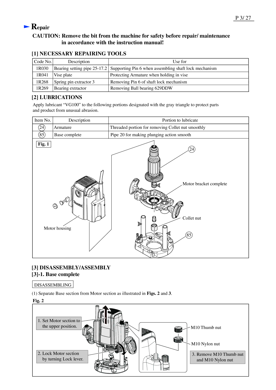
[2] LUBRICATIONS
Apply lubricant “VG100” to the following portions designated with the gray triangle to protect parts and product from unusual abrasion.
Item No. | Description | Portion to lubricate |
24 | Armature | Threaded portion for removing Collet nut smoothly |
85 | Base complete | Pipe 20 for making plunging action smooth |
Fig. 1 |
| 24 |
|
|
Motor bracket complete
Collet nut
Motor housing
85
[3]DISASSEMBLY/ASSEMBLY
[3]-1. Base complete
DISASSEMBLING
(1)Separate Base section from Motor section as illustrated in Figs. 2 and 3.
Fig. 2
1. Set Motor section to ![]() the upper position.
the upper position. ![]()
2. Lock Motor section by turning Lock lever.
![]() M10 Thumb nut
M10 Thumb nut
![]() M10 Nylon nut
M10 Nylon nut
3.Remove M10 Thumb nut and M10 Nylon nut