OTHER FUNCTIONS
How to use the CONTROL I/O
(control input/output) connector
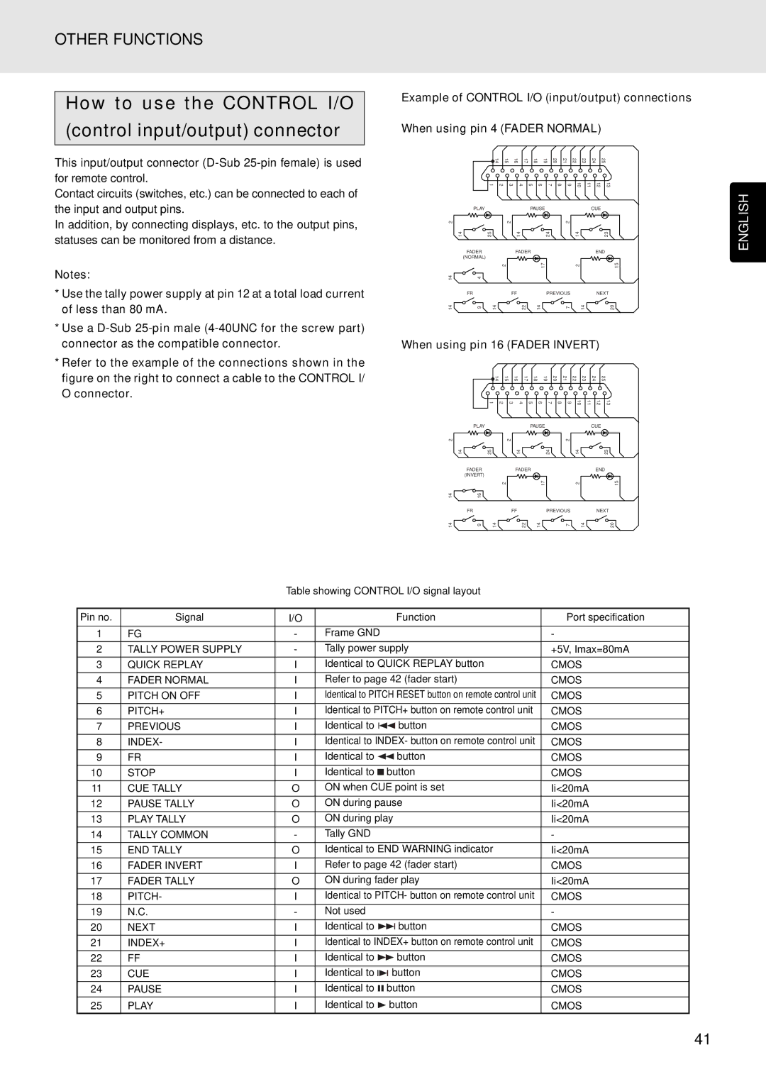
Example of CONTROL I/O (input/output) connections
When using pin 4 (FADER NORMAL)
This input/output connector
Contact circuits (switches, etc.) can be connected to each of the input and output pins.
In addition, by connecting displays, etc. to the output pins, statuses can be monitored from a distance.
14 | 15 |
| 16 | 17 | 18 | 19 | 20 |
| 21 | 22 | 23 | 24 | 25 |
1 | 2 | 3 | 4 | 5 | 6 |
| 7 | 8 | 9 | 10 | 11 | 12 | 13 |
| PLAY | PAUSE |
|
| CUE |
2 |
| 2 |
| 2 |
|
14 | 25 | 14 | 24 | 14 | 23 |
| FADER | FADER |
|
| END |
| (NORMAL) |
|
|
|
|
| 2 | 17 |
| 2 | 15 |
ENGLISH
Notes:
*Use the tally power supply at pin 12 at a total load current of less than 80 mA.
*Use a
*Refer to the example of the connections shown in the figure on the right to connect a cable to the CONTROL I/ O connector.
14 | 4 |
|
|
|
|
|
|
FR |
|
| FF |
| PREVIOUS |
| NEXT |
14 | 9 | 14 | 22 | 14 | 7 | 14 | 20 |
When using pin 16 (FADER INVERT)
14 | 15 |
| 16 | 17 | 18 | 19 | 20 |
| 21 | 22 | 23 | 24 | 25 |
1 | 2 | 3 | 4 | 5 | 6 |
| 7 | 8 | 9 | 10 | 11 | 12 | 13 |
| PLAY |
|
| PAUSE |
|
| CUE |
2 |
|
| 2 |
| 2 |
|
|
14 |
| 25 | 14 |
| 24 | 14 | 23 |
| FADER |
| FADER |
|
| END | |
| (INVERT) |
|
|
|
|
|
|
|
| 2 |
| 17 |
| 2 | 15 |
14 | 16 |
|
|
|
|
|
|
| FR |
| FF |
| PREVIOUS |
| NEXT |
14 | 9 | 14 | 22 | 14 | 7 | 14 | 20 |
Table showing CONTROL I/O signal layout
Pin no. | Signal | I/O |
|
| Function | Port specification |
|
|
|
|
|
|
|
1 | FG | - | Frame GND |
| - | |
|
|
|
|
|
| |
2 | TALLY POWER SUPPLY | - | Tally power supply | +5V, Imax=80mA | ||
|
|
|
|
|
| |
3 | QUICK REPLAY | I | Identical to QUICK REPLAY button | CMOS | ||
|
|
|
|
|
| |
4 | FADER NORMAL | I | Refer to page 42 (fader start) | CMOS | ||
|
|
|
|
|
| |
5 | PITCH ON OFF | I | Identical to PITCH RESET button on remote control unit | CMOS | ||
|
|
|
|
|
| |
6 | PITCH+ | I | Identical to PITCH+ button on remote control unit | CMOS | ||
|
|
|
|
|
|
|
7 | PREVIOUS | I | Identical to | button | CMOS | |
|
|
|
|
|
| |
8 | INDEX- | I | Identical to INDEX- button on remote control unit | CMOS | ||
|
|
|
|
|
|
|
9 | FR | I | Identical to | button | CMOS | |
|
|
|
|
|
|
|
10 | STOP | I | Identical to |
| button | CMOS |
| ||||||
| ||||||
|
|
|
|
| ||
11 | CUE TALLY | O | ON when CUE point is set | Ii<20mA | ||
|
|
|
|
| ||
12 | PAUSE TALLY | O | ON during pause | Ii<20mA | ||
|
|
|
|
| ||
13 | PLAY TALLY | O | ON during play | Ii<20mA | ||
|
|
|
|
|
| |
14 | TALLY COMMON | - | Tally GND |
| - | |
|
|
|
|
| ||
15 | END TALLY | O | Identical to END WARNING indicator | Ii<20mA | ||
|
|
|
|
| ||
16 | FADER INVERT | I | Refer to page 42 (fader start) | CMOS | ||
|
|
|
|
| ||
17 | FADER TALLY | O | ON during fader play | Ii<20mA | ||
|
|
|
|
| ||
18 | PITCH- | I | Identical to PITCH- button on remote control unit | CMOS | ||
|
|
|
|
|
| |
19 | N.C. | - | Not used |
| - | |
|
|
|
|
|
| |
20 | NEXT | I | Identical to | button | CMOS | |
|
|
|
|
| ||
21 | INDEX+ | I | Identical to INDEX+ button on remote control unit | CMOS | ||
|
|
|
|
|
| |
22 | FF | I | Identical to | button | CMOS | |
|
|
|
|
|
| |
23 | CUE | I | Identical to | button | CMOS | |
|
|
|
|
|
| |
24 | PAUSE | I | Identical to | button | CMOS | |
|
|
|
|
|
| |
25 | PLAY | I | Identical to | button | CMOS | |
41