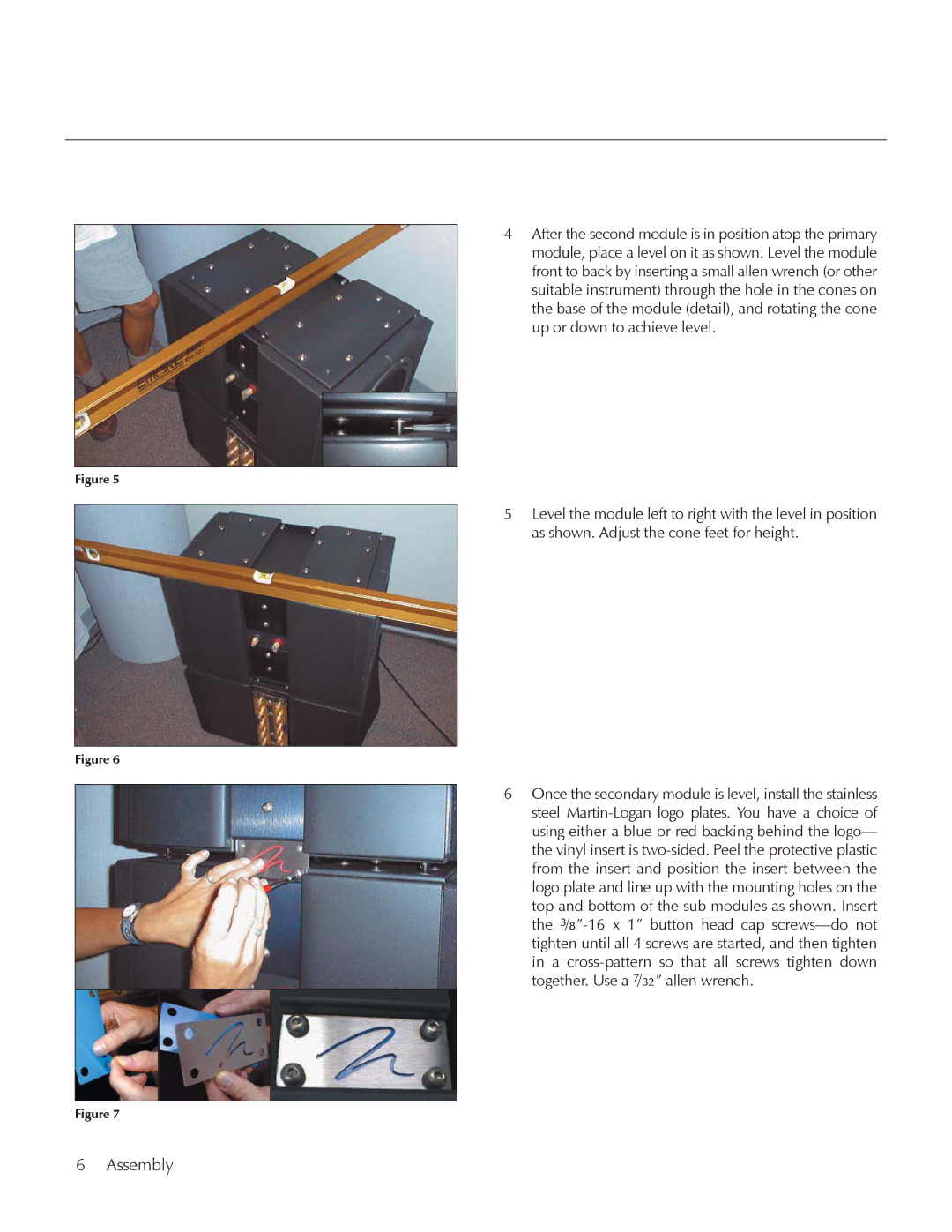
MartinLogan E2 manual Assembly

Models: E2

1 32
Download 32 pages 200 b
Page 6
Image 6
6 Assembly

Figure 5

Figure 6

Figure 7

4After the second module is in position atop the primary module, place a level on it as shown. Level the module front to back by inserting a small allen wrench (or other suitable instrument) through the hole in the cones on the base of the module (detail), and rotating the cone up or down to achieve level.

5Level the module left to right with the level in position as shown. Adjust the cone feet for height.

6Once the secondary module is level, install the stainless steel Martin-Logan logo plates. You have a choice of using either a blue or red backing behind the logo— the vinyl insert is two-sided. Peel the protective plastic from the insert and position the insert between the logo plate and line up with the mounting holes on the top and bottom of the sub modules as shown. Insert the 3/8”-16 x 1” button head cap screws—do not tighten until all 4 screws are started, and then tighten in a cross-pattern so that all screws tighten down together. Use a 7/32” allen wrench.

6 Assembly

Page 6
Image 6
MartinLogan E2 manual Assembly