Pin Specifications
Signal Input
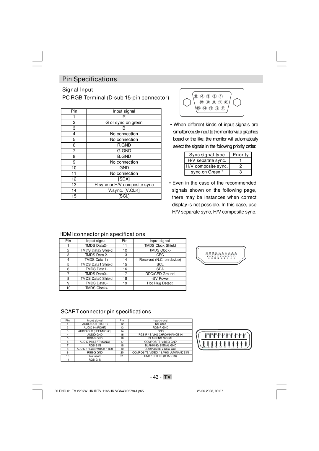
PC RGB Terminal (D-sub 15-pin connector)
Pin | Input signal |
1 | R |
2 | G or sync on green |
3 | B |
4 | No connection |
5 | No connection |
6 | R.GND |
7 | G.GND |
8 | B.GND |
9 | No connection |
10 | GND |
11 | No connection |
12 | [SDA] |
13 | H.sync or H/V composite sync |
14 | V.sync. [V.CLK] |
15 | [SCL] |
•When different kinds of input signals are simultaneouslyinputtothemonitorviaagraphics board or the like, the monitor will automatically select the signals in the following priority order:
Sync signal type | Priority |
H/V separate sync. | 1 |
H/V composite sync. | 2 |
sync.on Green * | 3 |
|
|
•Even in the case of the recommended signals shown on the following page, there may be instances when correct display is not possible. In this case, use H/V separate sync, H/V composite sync.
HDMI connector pin specifications
Pin | Input signal | Pin | Input signal |
1 | TMDS Data2+ | 11 | TMDS Clock Shield |
2 | TMDS Data2 Shield | 12 | TMDS Clock- |
3 | TMDS Data 2- | 13 | CEC |
4 | TMDS Data 1+ | 14 | Reserved (N.C. on device) |
5 | TMDS Data1 Shield | 15 | SCL |
6 | TMDS Data1- | 16 | SDA |
7 | TMDS Data0+ | 17 | DDC/CED Ground |
8 | TMDS Data0 Shield | 18 | +5V Power |
9 | TMDS Data0- | 19 | Hot Plug Detect |
10 | TMDS Clock+ |
|
|
SCART connector pin specifications
Pin | Input signal | Pin | Input signal |
1 | AUDIO OUT (RIGHT) | 12 | Not used |
2 | AUDIO IN (RIGHT) | 13 | |
3 | AUDIO OUT (LEFT/MONO) | 14 | GND |
4 | AUDIO GND | 15 | |
5 | 16 | BLANKING SIGNAL | |
6 | AUDIO IN (LEFT/MONO) | 17 | COMPOSITE VIDEO GND |
7 | 18 | BLANKING SIGNAL GND | |
8 | AUDIO / RGB SWITCH / 16:9 | 19 | COMPOSITE VIDEO OUT |
9 | 20 | COMPOSITE VIDEO / S.VHS LUMINANCE IN | |
10 | Not used | 21 | GND / SHIELD (CHASSIS) |
11 |
|
|
- 43 - ![]()
25.06.2008, 09:07 |