PRODUCT DESCRIPTION
Product Features
Functional / Interface
Maxtor hard drives contain all necessary mechanical and electronic parts to interpret control signals and commands from an
Zone Density Recording
The disk capacity is increased with bit density management – common with Zone Density Recording. Each disk surface is divided into 16 circumferential zones. All tracks within a given zone contain a constant number of data sectors. The number of data sectors per track varies in different zones; the outermost zone contains the largest number of data sectors and the innermost contains the fewest.
Read / Write Multiple Mode
This mode is implemented per ANSI
UltraDMA - Mode 5
Maxtor hard drives fully comply with the new ANSI Ultra DMA protocol, which greatly improves overall AT interface performance by significantly improving burst and sustained data throughput.
Supports
Sector Address Translation
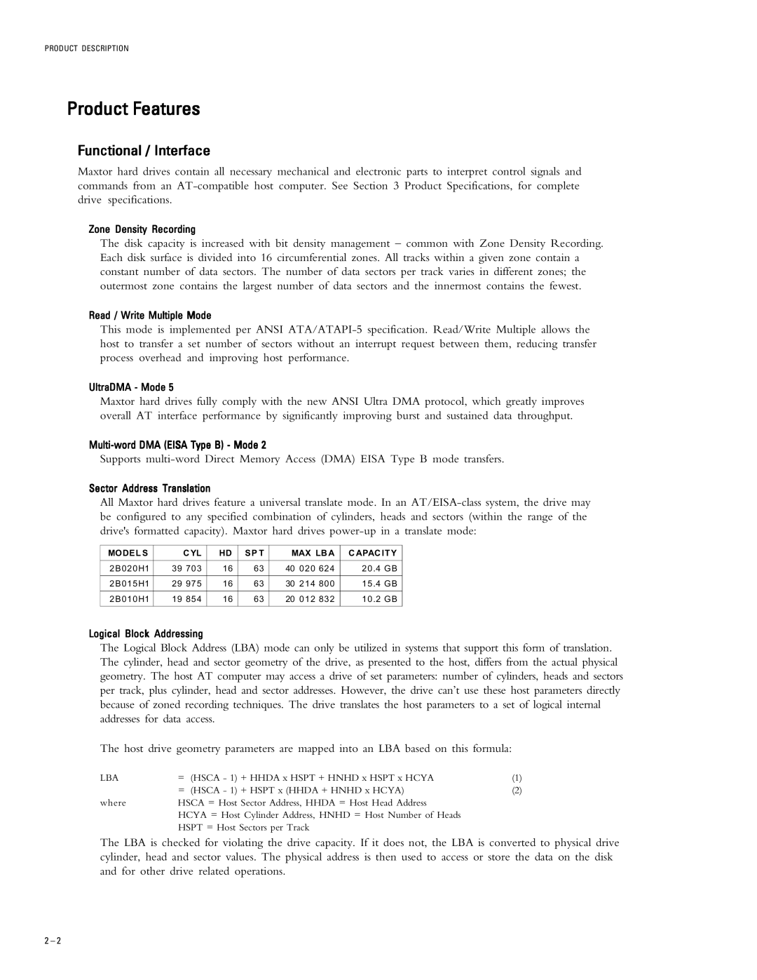
All Maxtor hard drives feature a universal translate mode. In an
MODELS | CYL | HD | SP T | MAX LBA | CAPACITY |
|
|
|
|
|
|
2B020H1 | 39 703 | 16 | 63 | 40 020 624 | 20.4 GB |
|
|
|
|
|
|
2B015H1 | 29 975 | 16 | 63 | 30 214 800 | 15.4 GB |
|
|
|
|
|
|
2B010H1 | 19 854 | 16 | 63 | 20 012 832 | 10.2 GB |
|
|
|
|
|
|
Logical Block Addressing
The Logical Block Address (LBA) mode can only be utilized in systems that support this form of translation. The cylinder, head and sector geometry of the drive, as presented to the host, differs from the actual physical geometry. The host AT computer may access a drive of set parameters: number of cylinders, heads and sectors per track, plus cylinder, head and sector addresses. However, the drive can’t use these host parameters directly because of zoned recording techniques. The drive translates the host parameters to a set of logical internal addresses for data access.
The host drive geometry parameters are mapped into an LBA based on this formula:
LBA | = (HSCA - 1) | + HHDA x HSPT + HNHD x HSPT x HCYA | (1) |
| = (HSCA - 1) | + HSPT x (HHDA + HNHD x HCYA) | (2) |
where | HSCA = Host Sector Address, HHDA = Host Head Address |
| |
| HCYA = Host Cylinder Address, HNHD = Host Number of Heads |
| |
| HSPT = Host Sectors per Track |
| |
The LBA is checked for violating the drive capacity. If it does not, the LBA is converted to physical drive cylinder, head and sector values. The physical address is then used to access or store the data on the disk and for other drive related operations.
2 – 2