AT INTERFACE DESCRIPTION
Pin Description Table
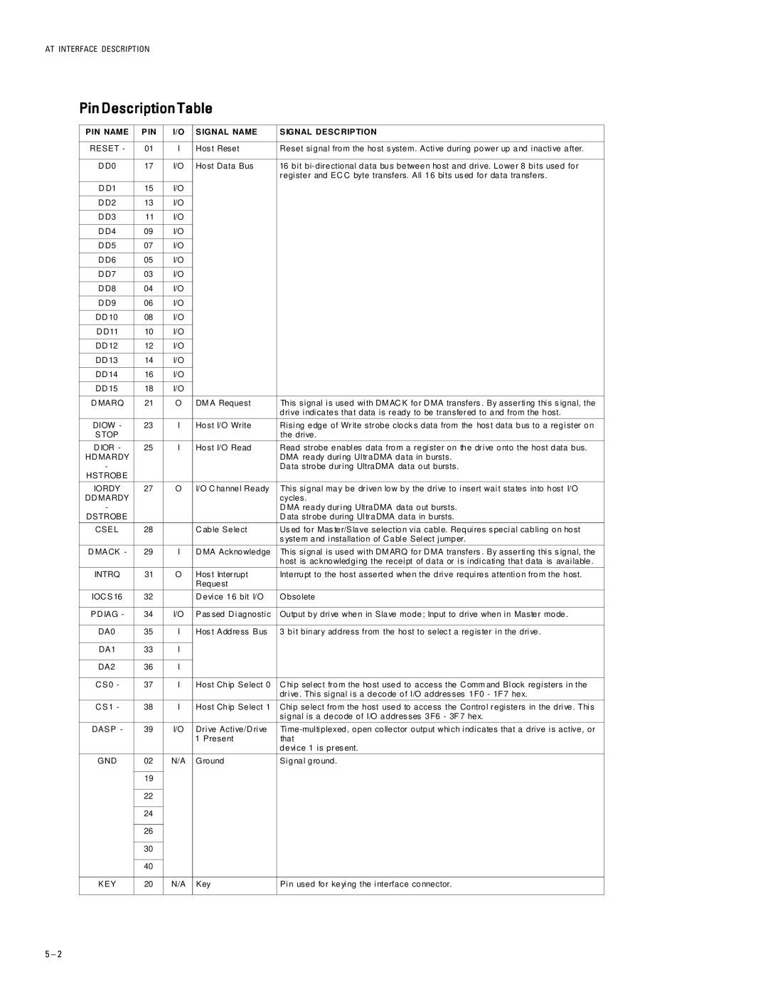
PIN NAME | PIN | I/O | SIGNAL NAME | SIGNAL DESC RIPTION |
|
|
|
|
|
RESET - | 01 | I | Hos t Reset | Reset signal from the host s ystem. Active during power up and inactive after. |
|
|
|
|
|
D D0 | 17 | I/O | Host Data Bus | 16 bit |
|
|
|
| register and EC C byte transfers. All 16 bits us ed for data transfers. |
|
|
|
|
|
D D1 | 15 | I/O |
|
|
|
|
|
|
|
D D2 | 13 | I/O |
|
|
|
|
|
|
|
D D3 | 11 | I/O |
|
|
|
|
|
|
|
D D4 | 09 | I/O |
|
|
|
|
|
|
|
D D5 | 07 | I/O |
|
|
|
|
|
|
|
D D6 | 05 | I/O |
|
|
|
|
|
|
|
D D7 | 03 | I/O |
|
|
|
|
|
|
|
D D8 | 04 | I/O |
|
|
|
|
|
|
|
D D9 | 06 | I/O |
|
|
|
|
|
|
|
DD 10 | 08 | I/O |
|
|
|
|
|
|
|
D D11 | 10 | I/O |
|
|
|
|
|
|
|
DD 12 | 12 | I/O |
|
|
|
|
|
|
|
DD 13 | 14 | I/O |
|
|
|
|
|
|
|
DD 14 | 16 | I/O |
|
|
|
|
|
|
|
DD 15 | 18 | I/O |
|
|
|
|
|
|
|
D MARQ | 21 | O | DM A Request | This signal is used with DM AC K for D MA transfers . By asserting this s ignal, the |
|
|
|
| drive indicates that data is ready to be transfered to and from the host. |
DIOW - | 23 | I | Host I/O Write | Rising edge of Write strobe clock s data from the hos t data bus to a register on |
STOP |
|
|
| the drive. |
D IOR - | 25 | I | Host I/O Read | Read strobe enables data from a register on the drive onto the host data bus. |
HD MARDY |
|
|
| DMA ready during UltraDMA data in bursts. |
- |
|
|
| Data strobe during UltraDMA data out bursts. |
HSTROBE |
|
|
|
|
|
|
|
|
|
IORDY | 27 | O | I/O C hannel Ready | This signal may be driven low by the drive to insert wait states into host I/O |
DD MARDY |
|
|
| cycles. |
- |
|
|
| D MA ready during UltraDMA data out bursts. |
DSTROBE |
|
|
| D ata strobe during UltraDMA data in bursts. |
CSEL | 28 |
| C able Select | Us ed for Mas ter/Slave selection via cable. Requires s pecial cabling on host |
|
|
|
| s ystem and installation of C able Select jumper. |
|
|
|
|
|
D MACK - | 29 | I | D MA Acknowledge | This signal is used with DM ARQ for D MA transfers . By asserting this s ignal, the |
|
|
|
| host is ac knowledging the receipt of data or is indicating that data is available. |
|
|
|
|
|
INTRQ | 31 | O | Hos t Interrupt | Interrupt to the host asserted when the drive requires attention from the host. |
|
|
| Request |
|
IOC S16 | 32 |
| D evice 16 bit I/O | Obsolete |
|
|
|
|
|
PD IAG - | 34 | I/O | Pas sed D iagnostic | Output by drive when in Slave mode; Input to drive when in Master mode. |
|
|
|
|
|
DA0 | 35 | I | Hos t Address Bus | 3 bit binary address from the host to selec t a regis ter in the drive. |
|
|
|
|
|
DA1 | 33 | I |
|
|
|
|
|
|
|
DA2 | 36 | I |
|
|
|
|
|
|
|
C S0 - | 37 | I | Host Chip Select 0 | C hip selec t from the host used to access the C omm and Block registers in the |
|
|
|
| drive. This signal is a decode of I/O addres ses 1F0 - 1F 7 hex. |
|
|
|
|
|
C S1 - | 38 | I | Host Chip Select 1 | Chip select from the host used to access the Control registers in the drive. This |
|
|
|
| signal is a decode of I/O addres ses 3F6 - 3F 7 hex. |
DASP - | 39 | I/O | Drive Active/D rive | |
|
|
| 1 Present | that |
|
|
|
| device 1 is pres ent. |
|
|
|
|
|
GND | 02 | N/A | Ground | Signal ground. |
|
|
|
|
|
| 19 |
|
|
|
|
|
|
|
|
| 22 |
|
|
|
|
|
|
|
|
| 24 |
|
|
|
|
|
|
|
|
| 26 |
|
|
|
|
|
|
|
|
| 30 |
|
|
|
|
|
|
|
|
| 40 |
|
|
|
|
|
|
|
|
KEY | 20 | N/A | Key | Pin used for keying the interface connector. |
|
|
|
|
|
5 – 2