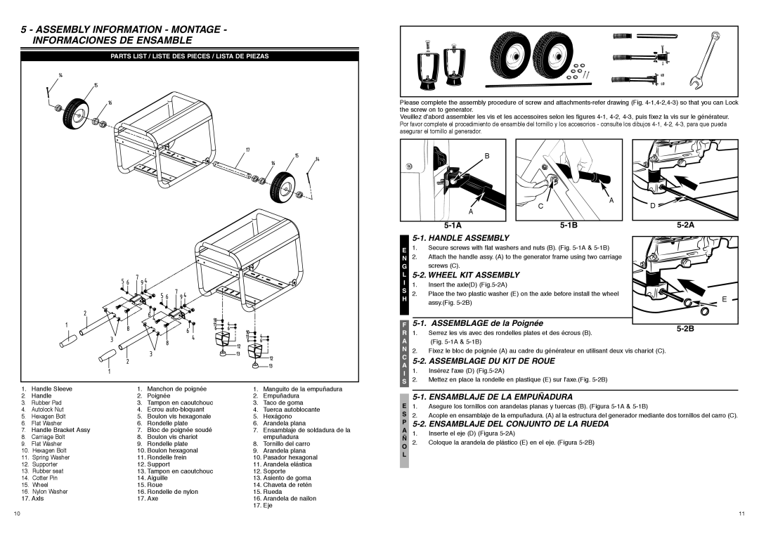
7096-FG7008, FG7000MA specifications
The McCulloch FG7000MA and 7096-FG7008 are two powerful and efficient garden tools designed for homeowners and professional landscapers alike. With their superior engineering and advanced technology, these models offer an unparalleled experience in lawn care and maintenance.The FG7000MA is known for its lightweight design, making it easy to maneuver while still delivering powerful performance. It is powered by a robust engine that provides ample power for tackling dense foliage and tough underbrush. This model features an adjustable cutting height, allowing users to customize their mowing experience based on the type of grass and lawn conditions they encounter, ensuring optimal cutting results every time.
Meanwhile, the 7096-FG7008 takes performance a step further with its advanced cutting technology. This model boasts a dual-blade system that significantly improves cutting efficiency and quality. The innovative design allows for a cleaner cut, reducing the likelihood of damaging grass blades and promoting healthier growth overall. Additionally, the 7096-FG7008 is equipped with a powerful motor that can easily handle even the most challenging terrain, making it a versatile choice for a variety of landscapes.
Both models come with user-friendly controls and ergonomic handles, ensuring that users can operate them comfortably for extended periods without experiencing fatigue. The FG7000MA and 7096-FG7008 also feature easy-start technology, allowing for quick and hassle-free ignition, a significant convenience for busy individuals looking to maximize their productivity.
Durability is another essential characteristic of these McCulloch models. Built with high-quality materials, they are designed to withstand the rigors of outdoor use, ensuring longevity and reliability. Maintenance is straightforward, with easy access to vital components for quick servicing.
In summary, the McCulloch FG7000MA and 7096-FG7008 stand out in the market for their combination of power, efficiency, and user-friendly features. With their advanced technologies, these models promise an exceptional mowing experience, whether you're tackling your own garden or managing large landscaping projects. Investing in either of these models will undoubtedly elevate your lawn care routine and deliver impressive results that you can see and appreciate throughout the seasons.

