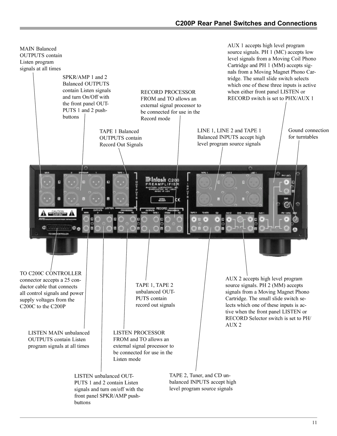
C200P Rear Panel Switches and Connections
MAIN Balanced OUTPUTS contain Listen program signals at all times
SPKR/AMP 1 and 2 Balanced OUTPUTS contain Listen signals and turn On/Off with the front panel OUT- PUTS 1 and 2 push- buttons
RECORD PROCESSOR FROM and TO allows an external signal processor to be connected for use in the Record mode
AUX 1 accepts high level program source signals. PH 1 (MC) accepts low level signals from a Moving Coil Phono Cartridge and PH 1 (MM) accepts sig- nals from a Moving Magnet Phono Car- tridge. The small slide switch selects which one of these three inputs is active when either front panel LISTEN or RECORD switch is set to PHX/AUX 1
TAPE 1 Balanced | LINE 1, LINE 2 and TAPE 1 | Gound connection |
OUTPUTS contain | Balanced INPUTS accept high | for turntables |
Record Out Signals | level program source signals |
|
TO C200C CONTROLLER connector accepts a 25 con- ductor cable that connects all control signals and power supply voltages from the C200C to the C200P
TAPE 1, TAPE 2 unbalanced OUT- PUTS contain record out signals
AUX 2 accepts high level program source signals. PH 2 (MM) accepts signals from a Moving Magnet Phono Cartridge. The small slide switch se- lects which one of these inputs is ac- tive when the front panel LISTEN or RECORD Selector switch is set to PH/ AUX 2
LISTEN MAIN unbalanced OUTPUTS contain Listen program signals at all times
LISTEN PROCESSOR FROM and TO allows an external signal processor to be connected for use in the Listen mode
LISTEN unbalanced OUT- PUTS 1 and 2 contain Listen signals and turn on/off with the front panel SPKR/AMP push- buttons
TAPE 2, Tuner, and CD un- balanced INPUTS accept high level program source signals
11