
C2200 specifications
The McIntosh C2200 is a high-fidelity vacuum tube preamplifier that exemplifies the brand's commitment to craftsmanship, performance, and timeless design. Known for its lush sound quality, the C2200 is a premier choice for audiophiles seeking to enhance their audio experience with the warmth and richness that only tube technology can provide.At the heart of the C2200 is a sophisticated vacuum tube circuit design, which significantly contributes to its sonorous and immersive audio output. The preamp employs 12AX7A dual triode tubes in its audio signal path, ensuring that music is delivered with exceptional clarity and detail. The incorporation of these tubes results in a pleasing harmonic distortion that many listeners find desirable, making the C2200 an appealing option for those who prefer the analog sound characteristics.
One of the key features of the McIntosh C2200 is its dual-mono configuration. This design allows the left and right audio channels to operate independently, minimizing crosstalk and ensuring a more accurate soundstage. Incorporating technologies such as the McIntosh Autoformer, the C2200 ensures consistent quality across various load impedances, which is pivotal for optimal audio performance.
This preamplifier is equipped with a variety of inputs, including five line-level inputs, a phono input for both moving coil and moving magnet cartridges, and a home theater bypass for integration into a multi-channel audio system. This versatility ensures that the C2200 can accommodate various sources, from turntables to digital players.
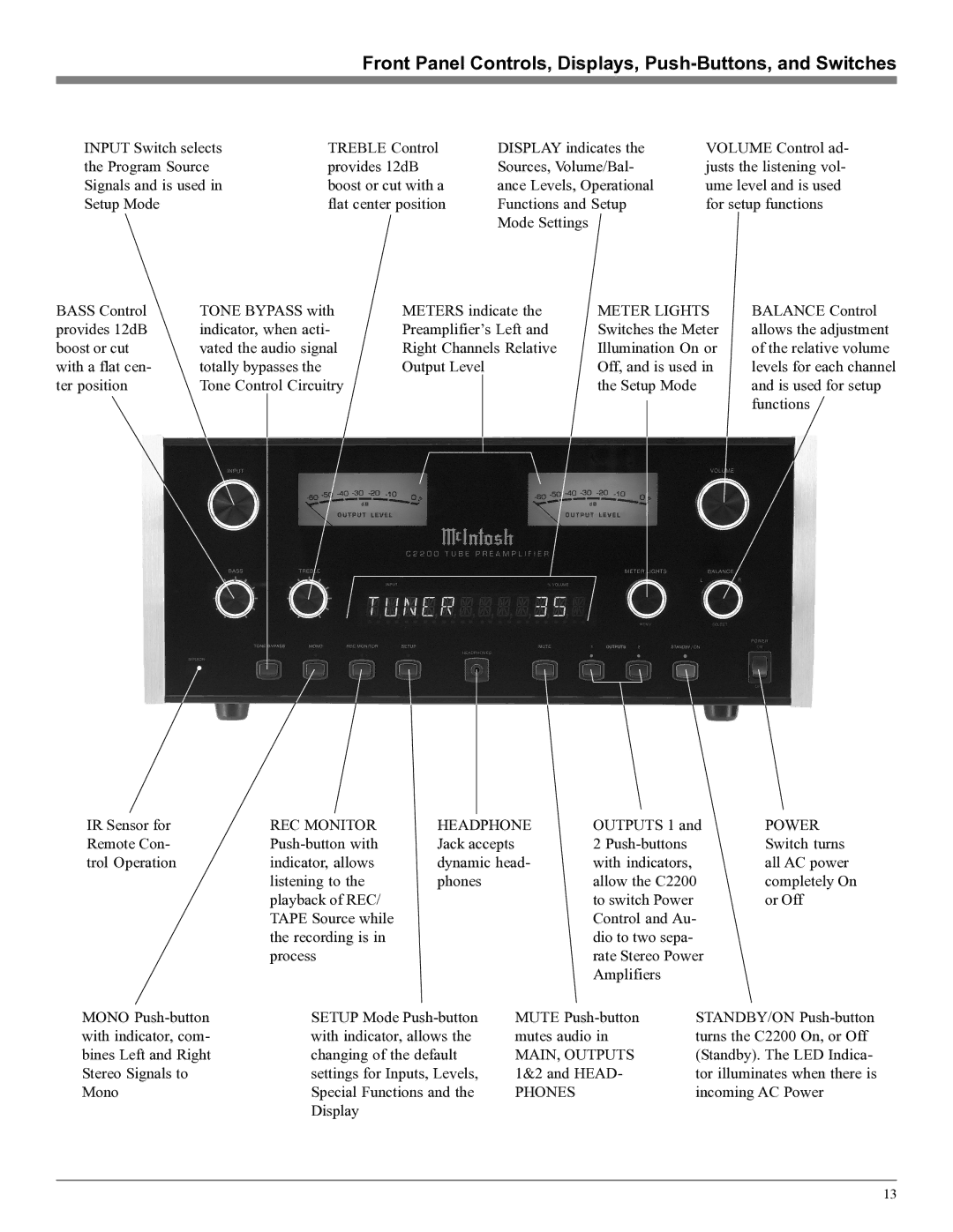
The user-friendly interface of the C2200 features a remote control, allowing effortless adjustments to volume and source selection from the comfort of your listening position. The beautiful glass front panel, illuminated by the iconic McIntosh blue meters, adds a stunning visual component, making the preamp not only an audio device but also an elegant piece of décor.
In terms of build quality, the C2200 is constructed with a robust chassis and high-grade components. The power supply is well-regulated, minimizing noise and ensuring that the audio signal remains uncolored. Additionally, the proprietary McIntosh power guard circuit prevents distortion and damage, promising years of reliable service.
Overall, the McIntosh C2200 stands as a remarkable achievement in audio engineering, offering audiophiles a unique blend of vintage tube warmth, modern technology, and unparalleled build quality. Whether used in a dedicated listening room or as part of a more comprehensive audio system, the C2200 delivers an aural experience that satisfies even the most discerning listeners.