1. Presentation
1.2 Rear panels
Pulsar MX 4000 RT / 5000 RT
SWITCHED | SWITCHED |
GROUP 2 | GROUP 1 |
7
8
9
11 | PARALLEL |
|
12
13
RS232 CONTACTS BAT NO. RPO
1
2
3
4
5
6
10
14
15
16
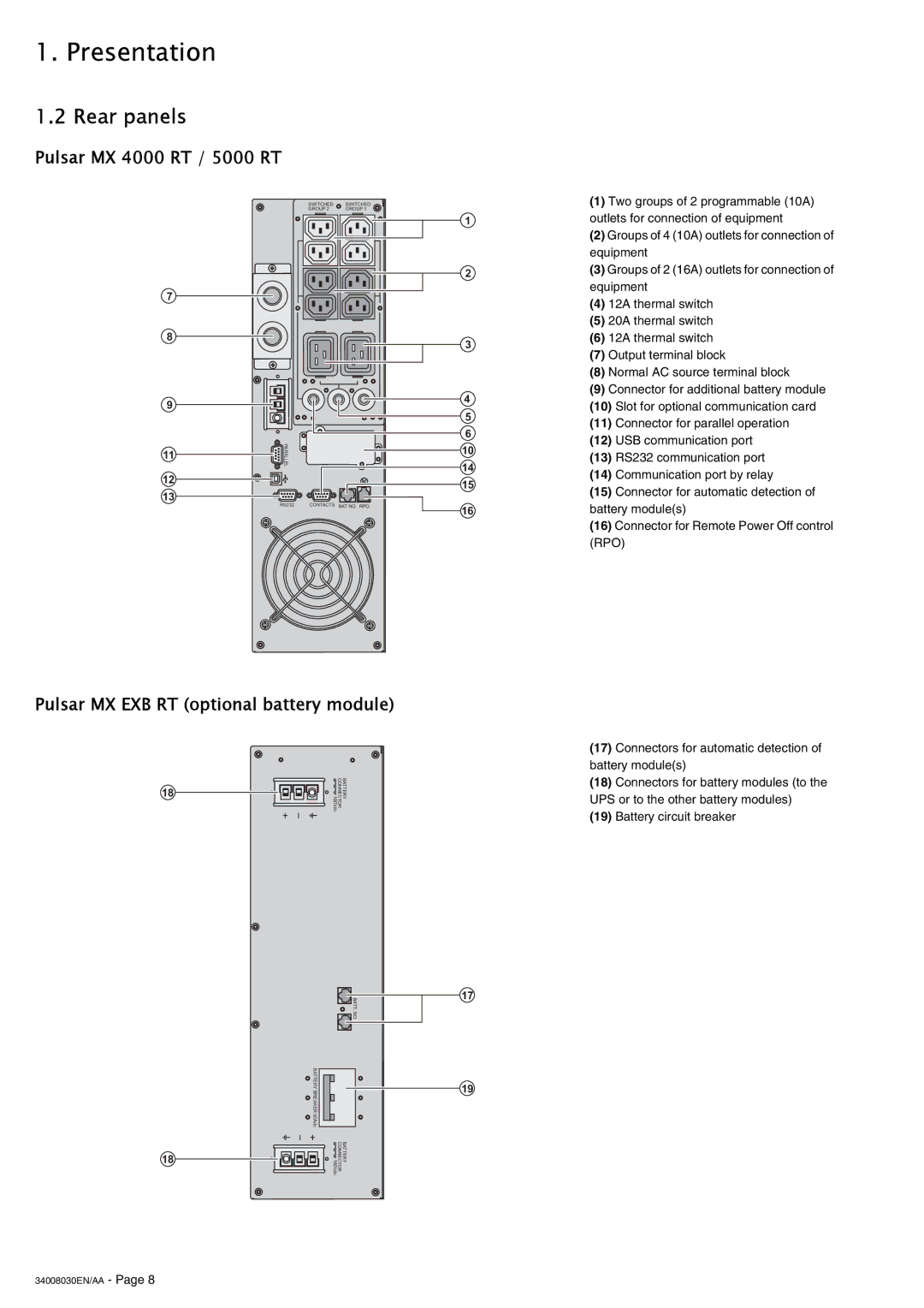
(1)Two groups of 2 programmable (10A) outlets for connection of equipment
(2)Groups of 4 (10A) outlets for connection of equipment
(3)Groups of 2 (16A) outlets for connection of equipment
(4)12A thermal switch
(5)20A thermal switch
(6)12A thermal switch
(7)Output terminal block
(8)Normal AC source terminal block
(9)Connector for additional battery module
(10)Slot for optional communication card
(11)Connector for parallel operation
(12)USB communication port
(13)RS232 communication port
(14)Communication port by relay
(15)Connector for automatic detection of battery module(s)
(16)Connector for Remote Power Off control (RPO)
Pulsar MX EXB RT (optional battery module)
18 ![]()
![]() 180Vdc
180Vdc![]() CONNECTORBATTERY
CONNECTORBATTERY
(17)Connectors for automatic detection of battery module(s)
(18)Connectors for battery modules (to the UPS or to the other battery modules)
(19)Battery circuit breaker
BATTERY BREAKER 50Adc
18
![]() BATT. NO.
BATT. NO.
BATTERY CONNECTOR 180Vdc
17
19
