EPS 7000 Single Module
ØOn/off | This pushbutton is reserved for future use. |
°Confirmation/Verify Depending on the displayed message, this pushbutton may serve to indicate confir- mation, positive response, and other functions.
1.5.2.3Numbered Lights
During normal operation, the green LED #1 will be on, indicating that the UPS core controller communicates with the display. If there is an alarm condition, the red LED #1 will turn on.
1.5.3Hidden Panel Indicators
The hidden panel is located behind the hinged cover, at the lowest pane of the front panel, refer to Figure
The hidden panel includes the alphanumeric display and controls, and following controls and indicators, see Figure
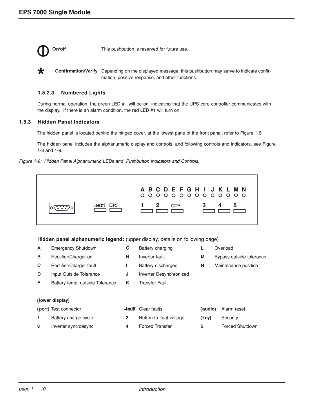
Figure 1-9: Hidden Panel Alphanumeric LEDs and Pushbutton Indicators and Controls.
A B C D E F G H I J K L M N
fault | 1 | 2 | 3 | 4 | 5 |
Hidden panel alphanumeric legend: (upper display, details on following page)
A | Emergency Shutdown | G | Battery charging | L | Overload |
B | Rectifier/Charger on | H | Inverter fault | M | Bypass outside tolerance |
C | Rectifier/Charger fault | I | Battery discharged | N | Maintenance position |
D | Input Outside Tolerance | J | Inverter Desynchronized |
|
|
F | Battery temp. outside Tolerance | K | Transfer Fault |
|
|
(lower display) |
|
|
|
| |
(port) Test connector | fault | Clear faults | (audio) Alarm reset | ||
1 | Battery charge cycle | 2 | Return to float voltage | (key) | Security |
3 | Inverter sync/desync | 4 | Forced Transfer | 5 | Forced Shutdown |
page 1 — 10 | Introduction |