Users Manual
1.5.1Front Panel
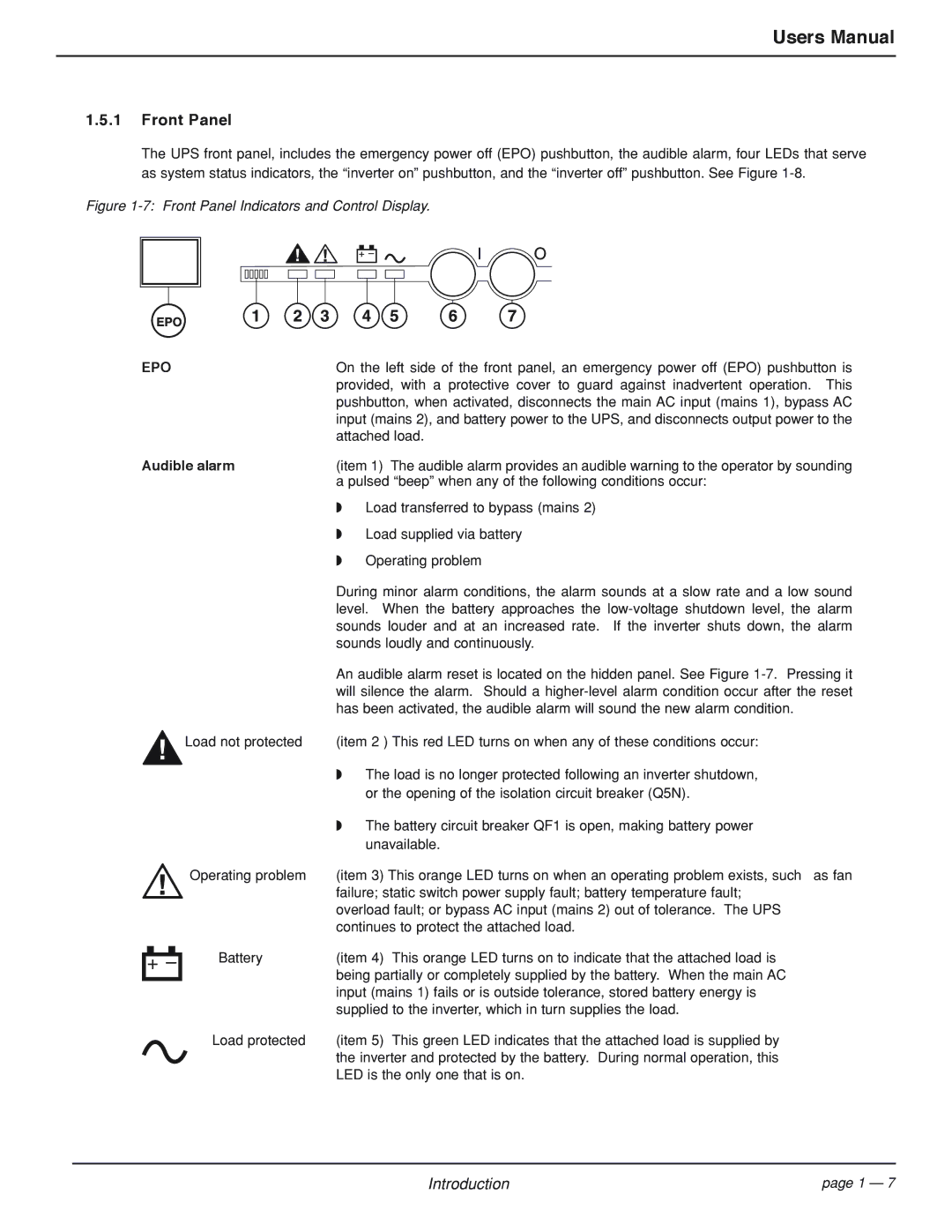
The UPS front panel, includes the emergency power off (EPO) pushbutton, the audible alarm, four LEDs that serve as system status indicators, the “inverter on” pushbutton, and the “inverter off” pushbutton. See Figure
Figure 1-7: Front Panel Indicators and Control Display.
EPO
On the left side of the front panel, an emergency power off (EPO) pushbutton is provided, with a protective cover to guard against inadvertent operation. This pushbutton, when activated, disconnects the main AC input (mains 1), bypass AC input (mains 2), and battery power to the UPS, and disconnects output power to the attached load.
Audible alarm | (item 1) The audible alarm provides an audible warning to the operator by sounding | |
| a pulsed “beep” when any of the following conditions occur: | |
| ◗ | Load transferred to bypass (mains 2) |
| ◗ | Load supplied via battery |
| ◗ | Operating problem |
| During minor alarm conditions, the alarm sounds at a slow rate and a low sound | |
| level. When the battery approaches the | |
| sounds louder and at an increased rate. If the inverter shuts down, the alarm | |
| sounds loudly and continuously. | |
| An audible alarm reset is located on the hidden panel. See Figure | |
| will silence the alarm. Should a | |
¡Load not protected | has been activated, the audible alarm will sound the new alarm condition. | |
(item 2 ) This red LED turns on when any of these conditions occur: | ||
| ◗ | The load is no longer protected following an inverter shutdown, |
|
| or the opening of the isolation circuit breaker (Q5N). |
| ◗ | The battery circuit breaker QF1 is open, making battery power |
|
| unavailable. |
Operating problem | (item 3) This orange LED turns on when an operating problem exists, such as fan | |
⁄ | failure; static switch power supply fault; battery temperature fault; | |
overload fault; or bypass AC input (mains 2) out of tolerance. The UPS | ||
continues to protect the attached load.
ı
Í
Battery | (item 4) This orange LED turns on to indicate that the attached load is |
| being partially or completely supplied by the battery. When the main AC |
| input (mains 1) fails or is outside tolerance, stored battery energy is |
| supplied to the inverter, which in turn supplies the load. |
Load protected | (item 5) This green LED indicates that the attached load is supplied by |
| the inverter and protected by the battery. During normal operation, this |
| LED is the only one that is on. |
Introduction | page 1 — 7 |