EPS 7000 Single Module
2.7Power Frequency Measurements
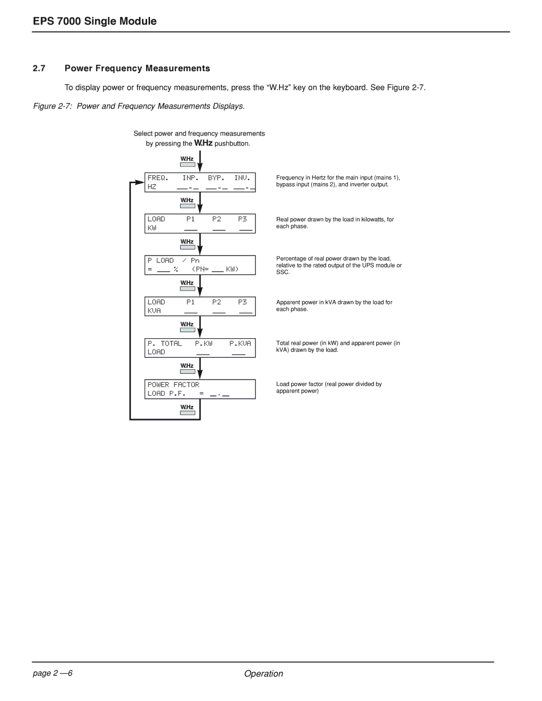
To display power or frequency measurements, press the “W.Hz” key on the keyboard. See Figure
Figure 2-7: Power and Frequency Measurements Displays.
Select power and frequency measurements by pressing the „ pushbutton.
„
FREQ. INP. BYP. INV. | Frequency in Hertz for the main input (mains 1), | |||||||||||
HZ |
|
|
|
|
|
|
|
|
|
|
| bypass input (mains 2), and inverter output. |
|
|
|
|
|
|
|
|
|
|
|
|
|
„
LOAD | P1 | P2 | P3 |
KW
„
P LOAD / Pn
=% (PN= KW)
„
LOAD P1 P2 P3 KVA
„
Real power drawn by the load in kilowatts, for each phase.
Percentage of real power drawn by the load, relative to the rated output of the UPS module or SSC.
Apparent power in kVA drawn by the load for each phase.
P. TOTAL | P.KW |
|
| P.KVA | |||||
LOAD |
|
|
|
|
|
|
|
| |
|
|
|
|
|
|
|
|
|
|
| „ |
|
|
|
|
|
|
|
|
|
|
|
|
|
|
|
|
|
|
|
|
|
|
|
|
|
|
|
|
POWER FACTOR |
|
|
|
|
| ||||
LOAD P.F. | = |
|
|
|
|
|
| ||
|
|
|
|
|
|
|
|
|
|
„
Total real power (in kW) and apparent power (in kVA) drawn by the load.
Load power factor (real power divided by apparent power)
page 2 | Operation |