getting started
installation
Comply with the safety rules indicated at the beginning of this document.
preliminary checklist
calways follow the Pulsar EX connection sequence explained in the following paragraphs;
ccheck that the information on the name plate 14 corresponds to your AC power and the power requirements of the loads that Pulsar EX will be supplying;
cif Pulsar EX is installed horizontally, mount is shown in figure 1, with the ventilation outlets on the top.
connecting Pulsar EX
cthe operations for connecting the connection modules, the "automatic bypass" and the Pulsar EXB battery extension modules, must be performed when Pulsar EX is shut down and disconnected from the AC power:
v power cable 5 not connected,
v battery switch 7 and battery circuit- breaker 32 open ("O" position),
v button 3 " " in the released position (load shutdown);
cthe connections on the terminal block are reserved for electrical installation specialists. For your safety, always connect the ground wires first.
crecommended wire
crecommended upstream protection:
Pulsar EX15/EX20:
Merlin Gerin C60N 10A C curve
Pulsar EX30/EX40:
Merlin Gerin C60N 16A C curve
cearthing system:
vPulsar EX is configured as standard in the TN earthing system in load output (grounded neutral with galvanic isolation),
vif Pulsar EX is fitted with the "automatic bypass" option, the downstream earthing system will be identical to the upstream earthing system (no galvanic isolation).
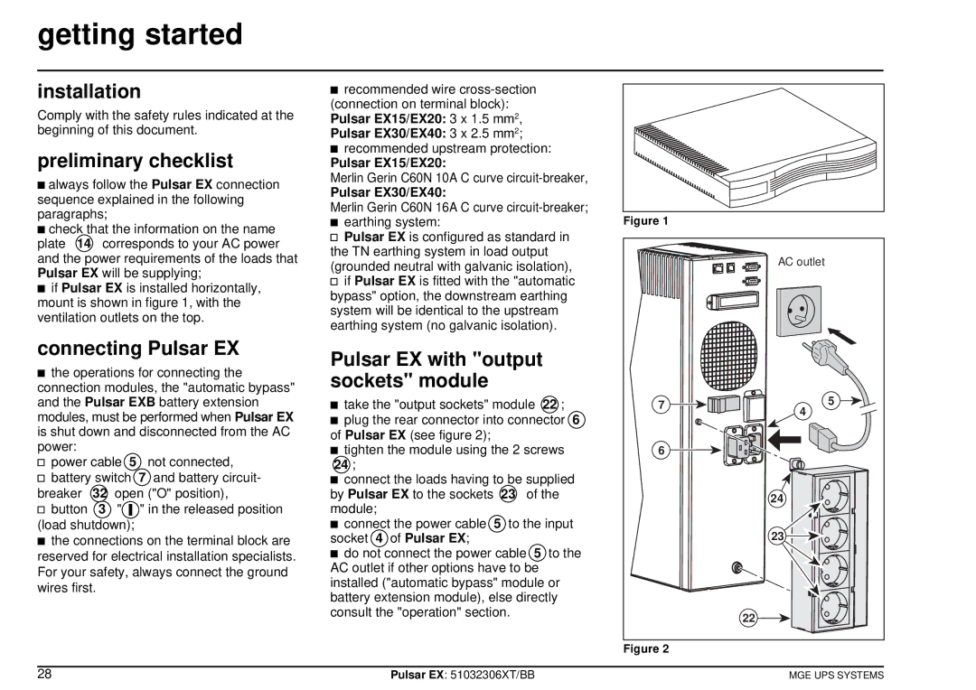
Pulsar EX with "output sockets" module
ctake the "output sockets" module 22 ;
cplug the rear connector into connector 6 of Pulsar EX (see figure 2);
ctighten the module using the 2 screws 24 ;
cconnect the loads having to be supplied by Pulsar EX to the sockets 23 of the module;
cconnect the power cable 5 to the input socket 4 of Pulsar EX;
cdo not connect the power cable 5 to the AC outlet if other options have to be installed ("automatic bypass" module or battery extension module), else directly consult the "operation" section.
Figure 1
| AC outlet | |
7 | 5 | |
4 | ||
| ||
6 |
| |
| 24 | |
| 23 | |
| 22 |
Figure 2
28 | Pulsar EX: 51032306XT/BB | MGE UPS SYSTEMS |