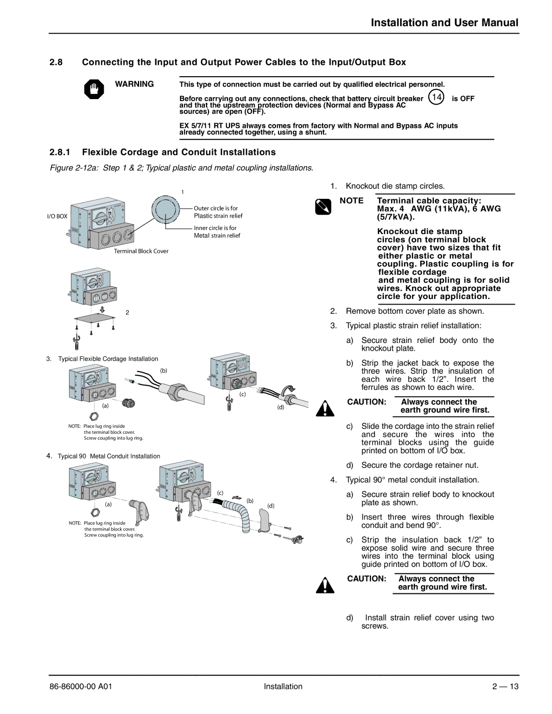
EX 7RT, EX 11RT, EX 5RT specifications
MGE UPS Systems, a prominent player in the uninterruptible power supply (UPS) sector, offers a range of high-performance models including the EX 5RT, EX 7RT, and EX 11RT. These systems are engineered to provide reliable power protection for critical applications across various segments such as IT, telecommunications, and industrial uses.The MGE EX 5RT, EX 7RT, and EX 11RT are designed with advanced technologies to ensure continuous operation even in the event of power disturbances. One of their standout features is the double-conversion online topology. This technology guarantees that the connected equipment receives stabilized power, free from voltage sags, surges, and frequency variations. The result is a consistent output voltage that caters to sensitive electronic systems.
These UPS systems are equipped with a wide input voltage range, allowing them to function effectively in environments with fluctuating power quality. This flexibility ensures that critical operations remain unimpeded even when the mains power supply experiences instability. Additionally, the systems have a high output power factor, which enhances efficiency and maximizes performance while reducing energy consumption.
Scalability is another key characteristic of the EX series. These models can be easily expanded and configured to meet growing power demands, making them suitable for both small and large applications. Integrated management software provides real-time monitoring and diagnostics, allowing users to take proactive measures to maintain system health and optimize performance.
The EX 5RT, EX 7RT, and EX 11RT also feature comprehensive battery management solutions. The systems employ intelligent charging technologies that prolong battery life and ensure dependable performance. Hot-swappable batteries simplify maintenance, enabling users to replace batteries without shutting down the entire system, thereby enhancing operational reliability.
Another notable aspect is their compact design, which allows for flexible installation in various environments. Whether rack-mounted or in a tower format, these UPS units can fit seamlessly into a range of settings. Furthermore, the units offer numerous connectivity options, including USB and serial ports, which facilitate integration with existing infrastructure.
In summary, MGE UPS Systems EX 5RT, EX 7RT, and EX 11RT provide comprehensive power protection through advanced technologies, scalable designs, and reliable performance. Their innovative features ensure that critical applications remain functional and secure, making them an ideal choice for organizations looking to safeguard their electronic investments.

