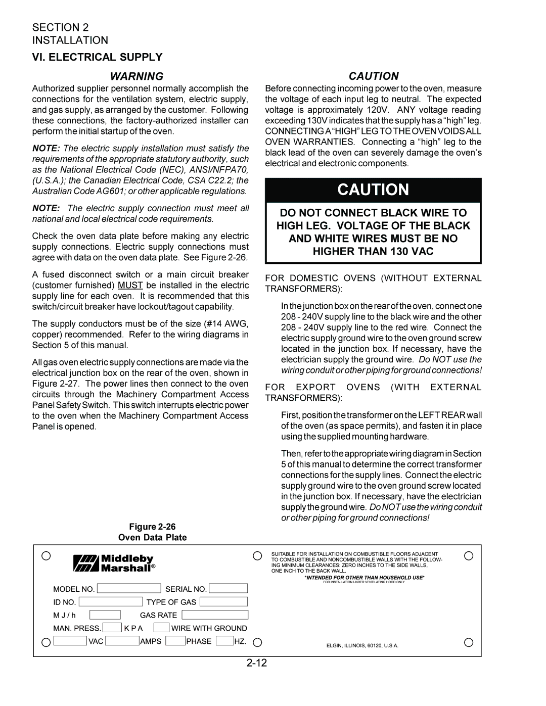
PS360, PS360WB specifications
The Middleby Marshall PS360 is a cutting-edge conveyor oven that revolutionizes the way restaurants and commercial kitchens approach food preparation. Specifically designed to enhance efficiency and optimize cooking processes, this oven has gained recognition for its ability to deliver consistently high-quality results in a fast-paced environment.One of the standout features of the PS360 is its innovative design that incorporates advanced forced air technology. This technology ensures even heat distribution throughout the cooking chamber, resulting in perfectly cooked pizzas, sandwiches, and other menu items without the need for frequent rotation. The forced air system also reduces cooking times, allowing for increased output, making it ideal for high-demand settings such as pizzerias and fast-casual dining establishments.
The PS360 is equipped with a user-friendly digital control panel that allows chefs to easily monitor and adjust cooking temperatures and times. This interface offers precise control over the cooking process, enabling users to customize settings based on specific recipes and customer preferences. Additionally, the oven features a range of programmable settings, allowing for quick adjustments that cater to varying menu items.
Another notable characteristic of the PS360 is its durable construction. Built with high-quality materials, it is designed to withstand the rigors of a busy kitchen environment. Its stainless steel exterior not only adds to its aesthetic appeal but also ensures easy cleaning and maintenance.
Safety is also a paramount concern for the Middleby Marshall PS360. The oven is designed with built-in safety features, including safety locks and temperature alerts, which help prevent accidents and ensure safe operation. The design also accommodates ventilation needs while maximizing energy efficiency, offering a sustainable solution for restaurants looking to reduce their carbon footprint.
Moreover, the PS360 is capable of handling a wide variety of menu items, from traditional pizzas to baked goods and roasted vegetables, making it a versatile addition to any kitchen. The ability to cook multiple items simultaneously streamlines kitchen operations and increases productivity.
In summary, the Middleby Marshall PS360 is a powerful and versatile conveyor oven that combines advanced technology, user-friendly features, and durable design. It enhances cooking efficiency, ensures consistent quality, and supports restaurants in delivering exceptional dishes to their customers. Whether for high-volume operations or varied menu needs, the PS360 stands out as an invaluable tool in commercial kitchens.

