ENGLISH
SECTION 2 - INSTALLATION
A.Gas Utility Rough-In Recommendations
The following gas system specifications are STRONGLY RECOMMENDED. Deviating from these recommendations may affect the baking performance of the oven.
Gas Meter
•One or two oven cavities: 354 l/sec meter
•Three or four oven cavities: 566 l/sec meter
Gas Line
•DEDICATED LINE from the gas meter to the oven
•50.8mm pipe for natural gas
•38.1mm pipe for propane
•Maximum length: 61m. Each 90° elbow equals 2.13m of pipe.
B.Connection
WARNING
Some procedures in this section may require conver- sions, readjustments, or service on the oven's gas system. Before performing these procedures, check that the main gas supply valve and the circuit breaker/fused disconnect are in the OFF ("O") position. After completing these proce- dures, perform a gas leak test before operating the oven.
CAUTION
The terms of the oven's warranty require all
NOTE: The gas supply connection should be according to applicable ISO
Check the oven’s gas supply requirements before making the gas utility connection. Gas supply requirements are listed on the oven’s serial plate.
Check the serial plate to determine the type of gas to be used with the oven. Check that the gas type indicated matches the local supply at the installation. If the gas type on the serial plate does NOT match the local supply, directions for converting the oven for use with other gases are described in Preparation for Use with Various Gases, in this section.
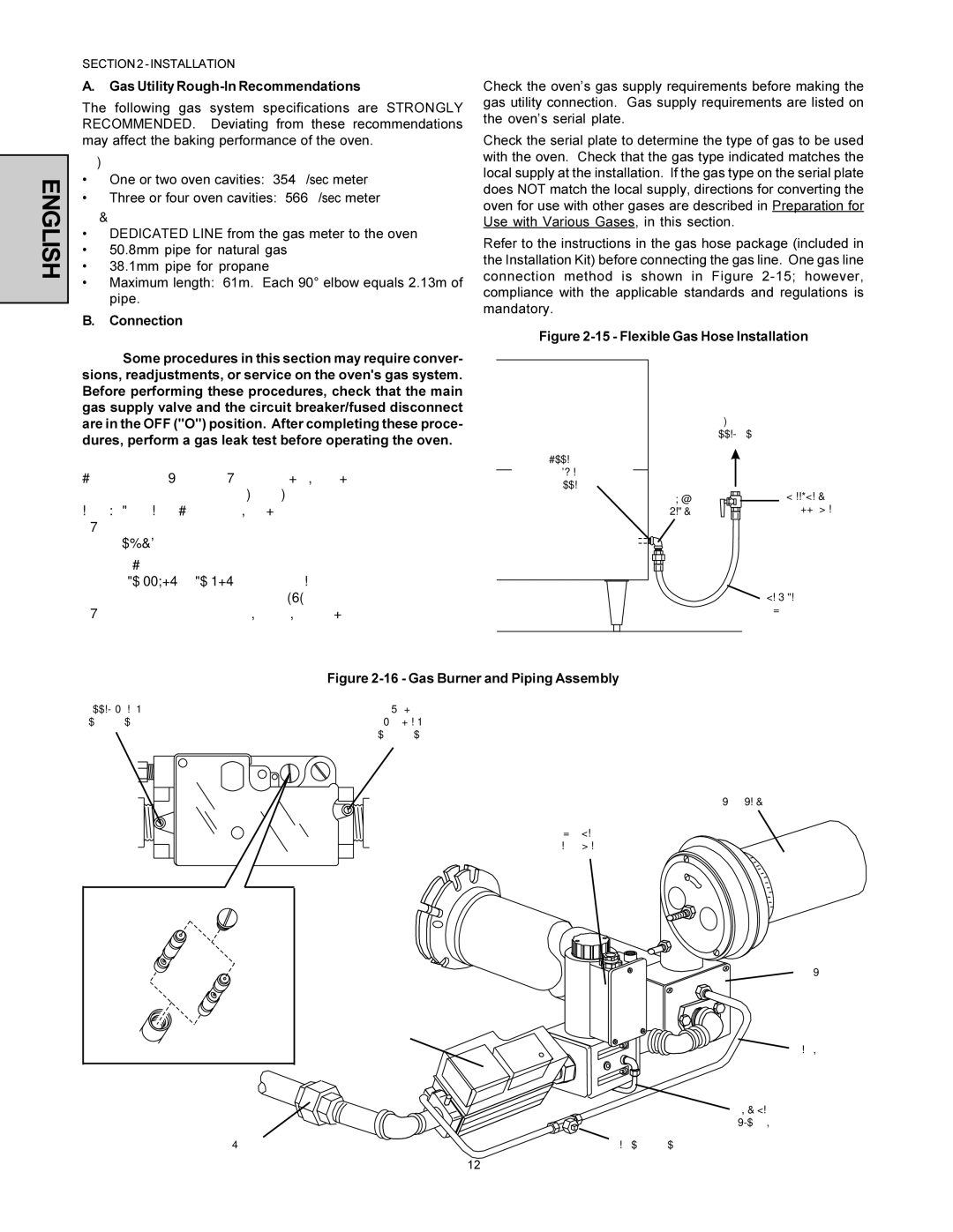
Refer to the instructions in the gas hose package (included in the Installation Kit) before connecting the gas line. One gas line connection method is shown in Figure
Figure 2-15 - Flexible Gas Hose Installation
To Gas
Supply Pipe
Appliance
Connection/Male
Nipple
90° | |
Elbow | Shutoff Valve |
Flexible
Gas Hose
Figure 2-16 - Gas Burner and Piping Assembly
Supply (inlet) | Orifice |
pressure tap | (manifold) |
Multifunction Gas Valve | pressure tap |
Burner Blower
High Flame
Solenoid Valve
Governor |
| |
disabled for |
| |
liquid |
| |
propane (LP) |
| |
operation |
| |
Governor | Multifunction | |
enabled for | ||
Gas Valve | ||
natural gas | ||
| ||
operation |
|
Gas Burner
Pilot Line
Low Flame
Bypass Line
Union | Pilot pressure tap |
12