Dedicated Video Game
Page
$6+27,0*2/,7,21 1/%/,7=*2/,7,21
Safety Instructions
Definitions of Safety Terms
Product Specifications
Equipment Characteristics
VGM Characteristics
Operating Requirements
Installation & Inspection
Install the Control Panel
Install the Door Lock and Security Brackets
Install the Line Cord
Setup
Operation
Video Game Machine VGM Operation
Starting UP
Custom Plays
Player Control Locations
Game Rules for NBA Showtime Gold Edition
Diagnostic Control Switch Locations
Diagnostic Control Switches
Operator Controls
Cabinet Controls
Maintenance
Servicing
Reinstalling Circuit Board Assemblies
Coin Mechanism
Memory
Cabinet Front View
Monitor
VGM ELECTRONICS, Internal Components
Monitor Bezel
Operation
DIAGNOSTIC, Audit Adjustment Menu System
What is the Menu SYSTEM?
Menu System
Activating the Menu System
Control Functions Menu
Main Menu
Dual Game Adjustment Menu
NFL Main Menu
Diagnostics
Diagnostics Menu
Diagnostics Menu
Exit Options
Monitor Setup
Diagnostics Menu Monitor Setup Menu
Monitor Setup Menu
System Information
Diagnostics Menu System Information Menu
System Information Menu
Sound Subsystem Test
Diagnostics Menu Sound Subsystem Menu
Sound Subsystem Menu
Disk Tests
Diagnostics Menu Disk Tests Menu
Disk Tests Menu
Diagnostics Menu Switch Tests Menu
Switch Tests
Player Switch Inputs Test
Switch Test Menu
Diagnostics Menu DIP Switch Tests Menu
DIP-SWITCH Tests
DIP Switch 1 U13
DIP Switch 2 U12
Speaker Test
Diagnostics Menu Speaker Test Menu
Speaker Test Menu
Audits
Audits Menu
Audits
Audits Menu
Coin Audits
Coin Audits
UP Next / Button Exit
Coin Audits MENU,
Audits Menu Credits Audits Menu
Credits Audits
Credits Audits
Credits Audits Menu
Game Audits
Down Prev / Button Exit
Team Stats
Audits Menu Team Stats Menu
Team Stats Menu
Audits Menu Offensive Plays Menu
Offensive Plays
Offensive Plays MENU,
Offensive Plays MENU,
Defensive Plays
Audits Menu Defensive Plays Menu
Defensive Plays Menu
Exception Dump
Clear Audits
Clear Audits
Clear Audits Menu
Adjustments
Adjustments
Pricing
Standard Pricing Table
Name Start Continue CREDITS/COIN Coin COIN4 Bill
Adjustments Menu Pricing Menu Current Pricing Menu
Standard Pricing Table
Current Pricing
Press ANY Button to Exit Current Pricing Menu
Custom Pricing
Adjustments Menu Pricing Menu Custom Pricing Menu
Custom Pricing Opening Menu
Creating
Custom Pricing Menu
Select Currency
Select Currency Menu page 2 of Creating Xxxx Menu
Pricing Menu Terms
Current Pricing Prompt Menu
Current Pricing Prompt
Screen Message Entry Menu Pricing Line
Save Pricing Scheme Menu
Adjustments Menu Attract Sound Menu
Adjustments Menu Free Play Menu
Attract Sound Menu
Adjustments Menu Additional Adjustments Menu
Additional Adjustments
Additional Adjustments
Additional Adjustments Menu
Adjustments Menu Full Factory Restore Menu
Full Factory Restore
Full Factory Restore Menu
Reset Completed Menu
SET Volume Level
Set Volume Level Menu
SET Volume Level Menu
SET Attract Volume Level
Set Attract Volume Level Menu
SET Attract Volume Level Menu
Utilities
Utilities Menu
Utilities
Utilities Menu
For NBA Showtime Games
Control Functions
NBA Main Menu
Diagnostics
0DLQ0HQXLDJQRVWLFVFRQWLQXHG0RQLWRU0HQX6HWXSFRQWLHG0HQX
System Information
Sound Subsystem Test
Disk Tests
Player Switch Inputs Test
DIP-SWITCH Tests
Speaker Test
Audits
Service Credits
Challenger Accepted
Free Quarters Awarded
Free Games Awarded
Credits Audits
Game Audits Menu
Team Stats
Game Features
Audits Menu Game Features Menu
Game Features MENU,
Diagnostic, Audit & Adjustment Menu System for NBA
Game Features MENU,
Main Menu
Adjustments
Standard Pricing Table
Current Pricing Menu
Custom Pricing
Creating
Pricing Menu Terms
Current Pricing Prompt
Custom Pricing
Attract Sound Menu
Additional Adjustments
Full Factory Restore
SET Volume Level
SET Attract Volume Level
Utilities
Wiring
Function Wire Color Pin
Solder Side of Circuit Board Function Wire Color Pin
Power Source Voltage Limits Function Range Limits
Function Wire Color SIO Bd, P3
Harness Connector Prefixes
Power Wiring Diagram
Cabinet Wiring Diagram
Control Panel Wiring Diagram
Control Wiring Diagram WAY Joystick Position Logic Table
CPU Board Indicator and Switch Locations CPU Board Switch
Switch Location Function Positions State Meaning
CPU Board Jumper Location Table
CPU Board Jumper Position Table
CPU Board LED Indicator Status Table
Device Location Function Color State Meaning
Sound I/O Board Assembly
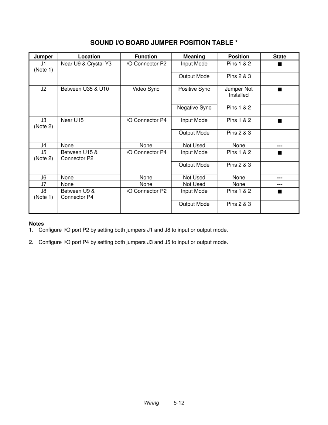
Sound I/O Board Jumper Position Table
Jumper Location Function Meaning Position State
LED
Sound I/O Board LED Indicator Status Table
Location Function Color State Meaning
Video Board Indicator and Jumper Locations
$6+27,0*2/,7,21 1/%/,7=*2/,7,21
Coin Mechanism and Pricing Troubleshooting Table
Symptom Cause Required Action
VGM Startup Troubleshooting Table
Front View Of Coin Door Interior View Of Electronics
Interior View of Coin Door and Cash Door
Audio Troubleshooting Table
Joystick Troubleshooting Table
Video Troubleshooting Table
Turn on VGM video game machine
To working VGM video game machine
Software Update Troubleshooting Table
Miscellaneous Problem Troubleshooting Table
Parts
Cabinet Front View
Monitor and Lamp Fixture Mounting
Cabinet Rear View
Rear Door Lock Detail
Rear Door Assembly A-20281
01-11287
Casters
LEG Levelers
Cabinet Decals
31-3586 31-3587 31-3483 31-3484 31-3491-1 31-1768 31-3492-1
Player Panel and Housing Decals
Marquee Header Mounting Detail
Player Panel Housing Installation
Player Panel & Housing Assembly A-23467
Player Panel Assembly A-23469
Player Panel Exploded View
WAY Joystick Assembly A-21939-1 and Button Assembly
Coin Door Exploded View
Coin Vault Parts
Electronics Assembly A-23781
Lamp Assembly A-22506
Power Supply
Sound I/O Card A-23704
CPU Board Assembly A-23702
Banshee Video Card
Auxiliary Adapter Card Assembly
Other Parts
Bulbs, Filters and Fuses
Line Cord Application Table
Part Number Country
USA
Typical I.E.C. Line Cord with Inline Female Plug
Coin Door Application Table
Parts
Page
For Service