. Complete Parts List available at www.MillerWelds.com
SECTION 7 − OPERATING AUXILIARY EQUIPMENT
7-1. Generator Power Panel Receptacles
|
|
|
|
|
|
|
|
|
|
|
|
|
|
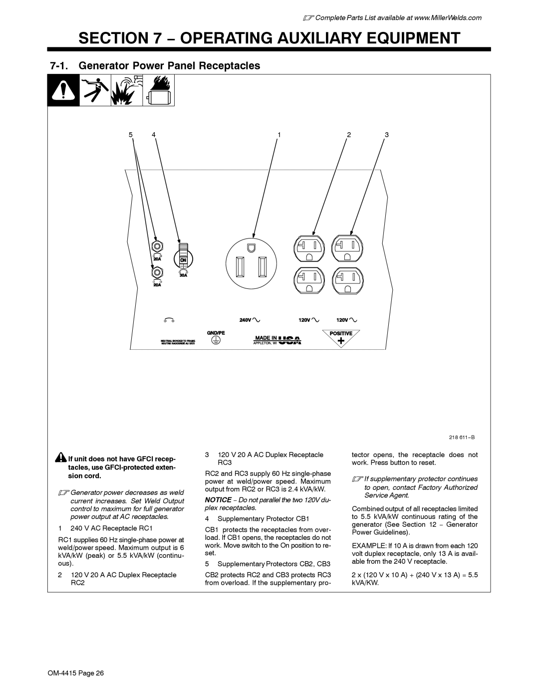
5 | 4 | 1 | 2 | 3 | ||
![]() If unit does not have GFCI recep- tacles, use
If unit does not have GFCI recep- tacles, use
.Generator power decreases as weld current increases. Set Weld Output control to maximum for full generator power output at AC receptacles.
1 240 V AC Receptacle RC1
RC1 supplies 60 Hz
2120 V 20 A AC Duplex Receptacle RC2
3120 V 20 A AC Duplex Receptacle RC3
RC2 and RC3 supply 60 Hz
NOTICE − Do not parallel the two 120V du- plex receptacles.
4 Supplementary Protector CB1
CB1 protects the receptacles from over- load. If CB1 opens, the receptacles do not work. Move switch to the On position to re- set.
5 Supplementary Protectors CB2, CB3
CB2 protects RC2 and CB3 protects RC3 from overload. If the supplementary pro-
218 611−B
tector opens, the receptacle does not work. Press button to reset.
.If supplementary protector continues
to open, contact Factory Authorized Service Agent.
Combined output of all receptacles limited to 5.5 kVA/kW continuous rating of the generator (See Section 12 − Generator Power Guidelines).
EXAMPLE: If 10 A is drawn from each 120 volt duplex receptacle, only 13 A is avail- able from the 240 V receptacle.
2 x (120 V x 10 A) + (240 V x 13 A) = 5.5 kVA/KW.