Visit our website at
www.MillerWelds.com
| 209 416F | ENGLISH | ||
| ||||
2007−05 |
|
|
|
|
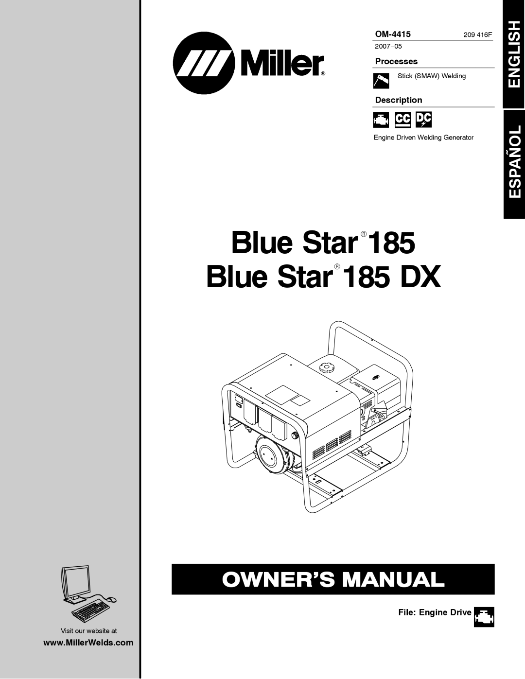
Processes |
|
|
|
|
|
|
|
| |
Stick (SMAW) Welding |
| |||
Description |
|
|
|
|
|
|
|
|
|
|
|
|
|
|
Engine Driven Welding Generator | ESPAÑOL | |||
| ||||
|
|
|
|
|
Blue StarR185
Blue StarR185 DX
Visit our website at
www.MillerWelds.com
| 209 416F | ENGLISH | ||
| ||||
2007−05 |
|
|
|
|
Processes |
|
|
|
|
|
|
|
| |
Stick (SMAW) Welding |
| |||
Description |
|
|
|
|
|
|
|
|
|
|
|
|
|
|
Engine Driven Welding Generator | ESPAÑOL | |||
| ||||
|
|
|
|
|
Blue StarR185
Blue StarR185 DX