5-8. Remote Receptacle Information
NOTE
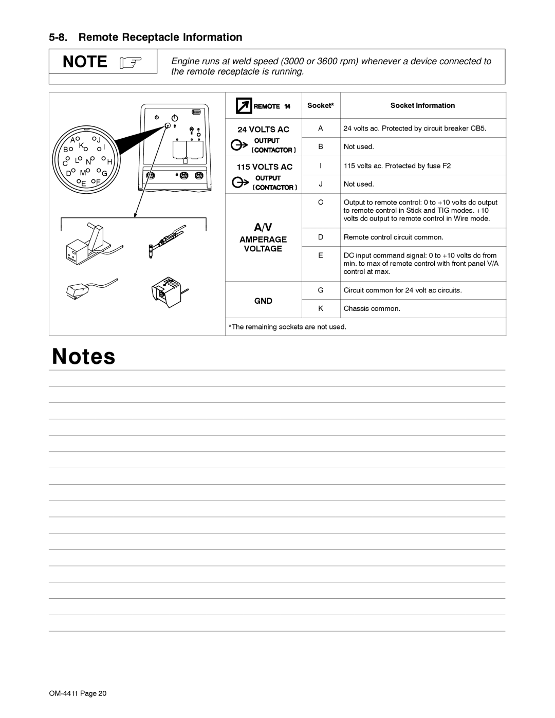
Engine runs at weld speed (3000 or 3600 rpm) whenever a device connected to the remote receptacle is running.
A K | J I | |
B |
|
|
C | L N | H |
D | M | G |
| E | F |
| Socket* | Socket Information | |
24 VOLTS AC | A | 24 volts ac. Protected by circuit breaker CB5. | |
| B | Not used. | |
115 VOLTS AC | I | 115 volts ac. Protected by fuse F2 | |
| J | Not used. | |
| C | Output to remote control: 0 to +10 volts dc output | |
|
| to remote control in Stick and TIG modes. +10 | |
A/V |
| volts dc output to remote control in Wire mode. | |
D | Remote control circuit common. | ||
AMPERAGE | |||
VOLTAGE | E | DC input command signal: 0 to +10 volts dc from | |
| |||
|
| min. to max of remote control with front panel V/A | |
|
| control at max. | |
| G | Circuit common for 24 volt ac circuits. | |
GND |
|
|
KChassis common.
*The remaining sockets are not used.
Notes