Manuals
/
Miller Electric
/
Power Tools
/
Welding System
Miller Electric
301 G
manual
211 395-C
Models:
301 G
1
43
60
60
Download
60 pages
53.22 Kb
40
41
42
43
44
45
46
47
Troubleshooting
Specs
Install
Electrical Diagram
Symbol Usage
Connecting The Battery
Main Assembly
Do not overfill battery cells
Process Switch Settings
Servicing Air Cleaner
Page 43
Image 43
211
395-C
OM-4411
Page 39
Page 42
Page 44
Page 43
Image 43
Page 42
Page 44
Contents
Processes
OM-4411207 283E
Description
From Miller to You
Table of Contents
Options and Accessories Warranty
Arc Welding Hazards
Symbol Usage
Engine Hazards
Compressed Air Hazards
Radiation can cause interference
Principal Safety Standards
California Proposition 65 Warnings
EMF Information
LES Fumées ET LES GAZ peuvent être dangereux
Signification des symboles
− Consignes DE Sécurité − Lire Avant Utilisation
UN Choc Électrique peut tuer
LE Bruit peut affecter l’ouïe
LE Soudage peut provoquer un in- cendie ou une explosion
DES Particules Volantes peuvent blesser les yeux
DES Pièces Chaudes peuvent provoquer des brûlures graves
’AIR Comprimé peut provoquer des blessures
’EXPLOSION DE LA Batterie peut
DES Organes Mobiles peuvent provoquer des blessures
LA Chaleur DU Moteur peut pro- voquer un incendie
Information sur les champs électromagnétiques
Principales normes de sécurité
− Definitions
Symbol Definitions
Description
− Specifications
Weld, Power, And Engine Specifications
Dimensions, Weights, and Operating Angles
Generator Power Curve
Fuel Consumption While Welding And Using Generator Power
Duty Cycle
Exceeding duty cycle can damage unit and void warranty
100% Duty Cycle at 280 Amperes DC/CC
CC/DC Stick Mode
Stick And MIG Mode Volt-Ampere Curves
CV/DC MIG Mode
DC TIG Mode Volt-Ampere Curves
Installing Welding Generator
− Installation
Oil
Engine Prestart Checks
Full Gasoline
Charger
Activating The Dry Charge Battery If Applicable
Do not overfill battery cells
Read and follow all instruc
Connect negative − cable last
Connecting The Battery
Installing Exhaust Pipe
+ −
Selecting Weld Cable Sizes
Connecting To Weld Output Terminals
Socket Information
Remote Receptacle Information
For wetter weld puddle for mild steel
Adjusting Wire MIG Weld Puddle Consistency
Reinstall side panel OM-4411
Tools Needed 7/16
Front Panel Controls
− Operating Welding Generator
Weld Output
Generator Power Output
Description Of Front Panel Controls
Engine Speed
Process Switch Settings
Process Switch
Switch Setting Process Output On/Off Control
Example Combination Remote Amperage Control Stick
Remote Amperage/Voltage Control
Circuit Breaker CB3
Hz Generator Power Receptacles And Circuit Breakers
− Operating Auxiliary Equipment
240 V 50 a AC Receptacle RC1
AC Receptacle RC3
Variable Frequency Hz Generator Power Receptacle RC3
Ceptacle RC3
120 V 20 a Variable Frequency
Receptacle
Current Available in Amperes
− Maintenance & Troubleshooting
Maintenance Label Servicing Optional Spark Arrestor
Oil
Servicing Air Cleaner
Full Tools Needed
Changing Engine Oil, Oil Filter, And Fuel Filter
Located behind front panel Tools Needed
Overload Protection
Circuit Breaker CB5
Welding
Troubleshooting
Trouble Remedy
Variable Frequency Generator Power Receptacle RC3
Hz Generator Power Receptacles RC1 And RC2
Engine
Start Your Professional Welding Career Now
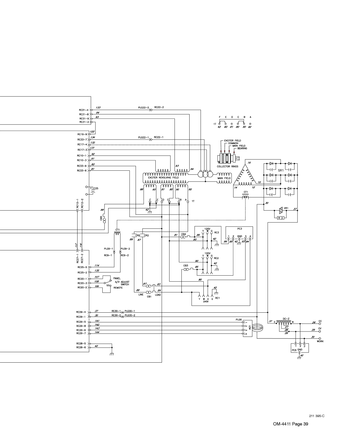
Circuit Diagram For Welding Generator
− Electrical Diagram
211 395-C
Selecting Equipment
− Generator Power Guidelines
Grounding Generator To Truck Or Trailer Frame
Amperes x Volts = Watts
Grounding When Supplying Building Systems
How Much Power Does Equipment Require?
Earth ground if supplying
Farm/Home Equipment Rating Starting Watts Running Watts
Approximate Power Requirements For Industrial Motors
Approximate Power Requirements For Farm/Home Equipment
Industrial Motors Rating Starting Watts Running Watts
Contractor Rating Starting Watts Running Watts
Approximate Power Requirements For Contractor Equipment
KVA/HP x HP x 1000 = Starting Amperage
Power Required To Start Motor
How Much Power Can Generator Supply?
Single-Phase Induction Motor Starting Requirements
Typical Connections To Supply Standby Power
Current Load Watts Amperes
Selecting Extension Cord Use Shortest Cord Possible
Material Thickness Reference Chart
− -3 41− -4
Main Assembly
Batt
182367
Panel Front w/Components -1Item
Panel Front w/Components
Panel, Front w/Components
Bracket w/Components
Generator -1Item
Your distributor also gives
Service
Support
Transportation Department
Miller Electric Mfg. Co
For assistance in filing or settling claims, contact
Your distributor and/or equipment manufacturer’s
Top
Page
Image
Contents