|
|
|
| |
|
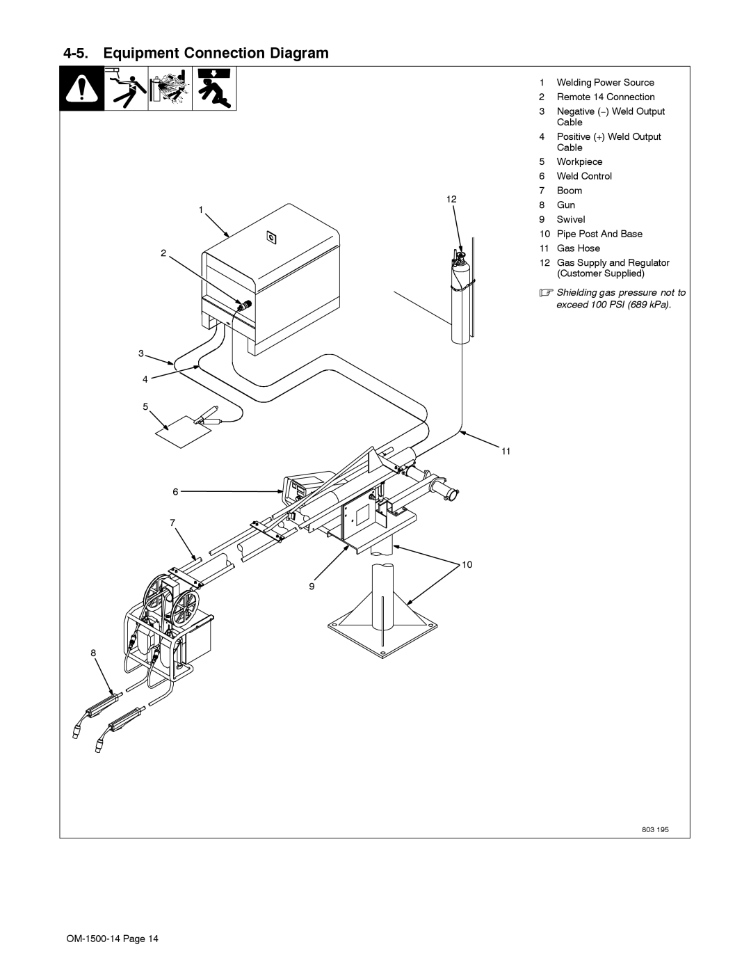
| 1 | Welding Power Source | |
|
| 2 | Remote 14 Connection | |
|
| 3 | Negative (−) Weld Output | |
|
|
| Cable | |
|
| 4 | Positive (+) Weld Output | |
|
|
| Cable | |
|
| 5 | Workpiece | |
|
| 6 | Weld Control | |
| 12 | 7 | Boom | |
1 | 8 | Gun | ||
| ||||
| 9 | Swivel | ||
|
| |||
|
| 10 | Pipe Post And Base | |
2 |
| 11 | Gas Hose | |
| 12 | Gas Supply and Regulator | ||
|
| |||
|
|
| (Customer Supplied) | |
|
| . Shielding gas pressure not to | ||
|
|
| exceed 100 PSI (689 kPa). | |
3 |
|
|
| |
4 |
|
|
| |
5 |
|
|
| |
|
| 11 |
| |
6 |
|
|
| |
7 |
|
|
| |
|
| 10 |
| |
9 |
|
|
| |
8 |
|
|
| |
|
|
| 803 195 | |
|
|
|
| |